FLEXLINE-CAD_INM.pdf - 第121页
C-1 A ppendix C D efault Format ♦ Si mple T ext F ormat (STF) Simple T ext Format is a format developed for users needing production files for older style JUKI machines. STF works in two different w ays: 1) If you need t…
B-4
Transformation takes place when any of the following parameters changes:
1. PCB Transport direction
“Left to Right” is changed to “Right to Left.”
2. PCB transport reference
“Front” is changed to “Rear.”
• PCB layout offset changes according to the following equations:
• Transport direction is changed to “Right to Left”
LX ′ = LX - KSX
• Reference is changed to “Rear reference”
LY ′ = KSY + LY
1. Changing PCB transport direction:
• PCB pin or edge reference changes according to the following conditions and equations:
Front reference:
Left to Right transport direction is changed to Right to Left transport direction:
PX ′ = - ((KSX - HX) - TX)
Right to Left transport direction is changed to Left to Right transport direction:
PX ′ = + ((KSX - HX) - TX)
Rear reference:
Right to Left transport direction is changed to Left to Right transport direction:
PX ′ = + ((KSX - HX) - TX)
Left to Right transport direction is changed to Right to Left transport direction:
PX ′ = - ((KSX - HX) - TX)
2. Changing PCB transport reference:
• PCB pin or edge reference changes according to the following conditions and equations:
Left to Right direction:
Front reference is changed to Rear reference:
PY ′ = + ((KSY - HY) - TY)
Rear reference is changed to Front reference:
PY ′ = - ((KSY - HY) - TY)
Right to Left direction:
Front reference is changed to Rear reference:
PY ′ = + ((KSY - HY) - TY)
Rear reference is changed to Front reference:
PY ′ = - ((KSY - HY) - TY)
C-1
Appendix C Default Format
♦
Simple Text Format (STF)
Simple Text Format is a format developed for users needing production files for older style JUKI
machines. STF works in two different ways:
1) If you need to convert a production file from an newer JUKI machine to an older JUKI
machine, Flexline CAD can generate a Simple Text Format to be read by Version 3.62 of
FlexProgram (old CAD conversion system) so that it can be used in the older machines.
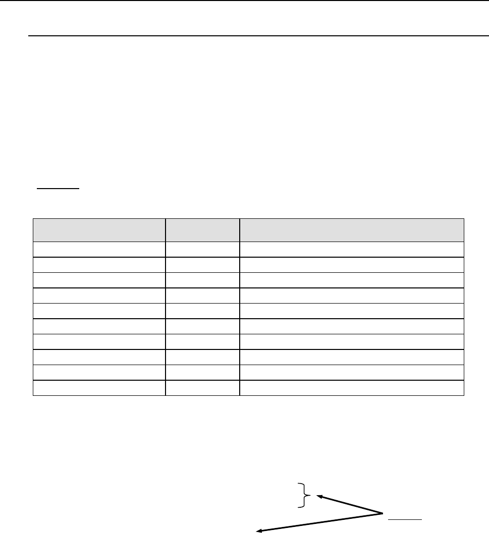
2) Because of the simplicity of STF, a user can also use it as an input format. The schema for
STF is as follows:
* Schema: Describes the order of field arrangement. This is used as the basis for Flexline
CAD to recognize CAD data.
Data item
Schema
identifier
Tag
PCB ID
Id
Comment lines tagged with PCB FIELDS
PCB reference coordinate X
Ref-x
Comment lines tagged with PCB FIELDS
PCB reference coordinate Y Ref-y Comment lines tagged with PCB FIELDS
BOC position 1X to 3X Boc-x Comment lines tagged with PCB FIELDS
BOC position 1Y to 3Y
Boc-y
Comment lines tagged with PCB FIELDS
Placement position X
X
Comment lines tagged with PLACEMENT FIELDS
Placement position Y
Y
Comment lines tagged with PLACEMENT FIELDS
Placement angle Y Rotation Comment lines tagged with PLACEMENT FIELDS
Placement ID
Id
Comment lines tagged with PLACEMENT FIELDS
Component name
Name
Comment lines tagged with PLACEMENT FIELDS
The following is a Simple Text Format data file that is compatible with Version 3.62 of
FlexlineProgram. Line 3, line 4, and line 6 correspond to the schema.
! SIMPLE TEXT FORMAT VERSION 1.0
!
! PCB FIELDS - id, ref-x, ref-y, boc-x, boc-y, boc-x, boc-y,
! boc-x, boc-y,
! Schema
! PLACEMENT FIELDS - x, y, rotation, id, name,
!
Single Board id, 140.000, 0.000, 130.000, 120.000, 1.000, 2.000, 3.000, 4.000
12.000, 12.000, 0.000,F1,COMP #1,
33.000, 33.000, 0.000,F2,COMP #2,
55.000, 55.000, 0.000,F3,COMP #3,
C-2
♦
TANGO
This format is mainly used in the U.S.A.
●
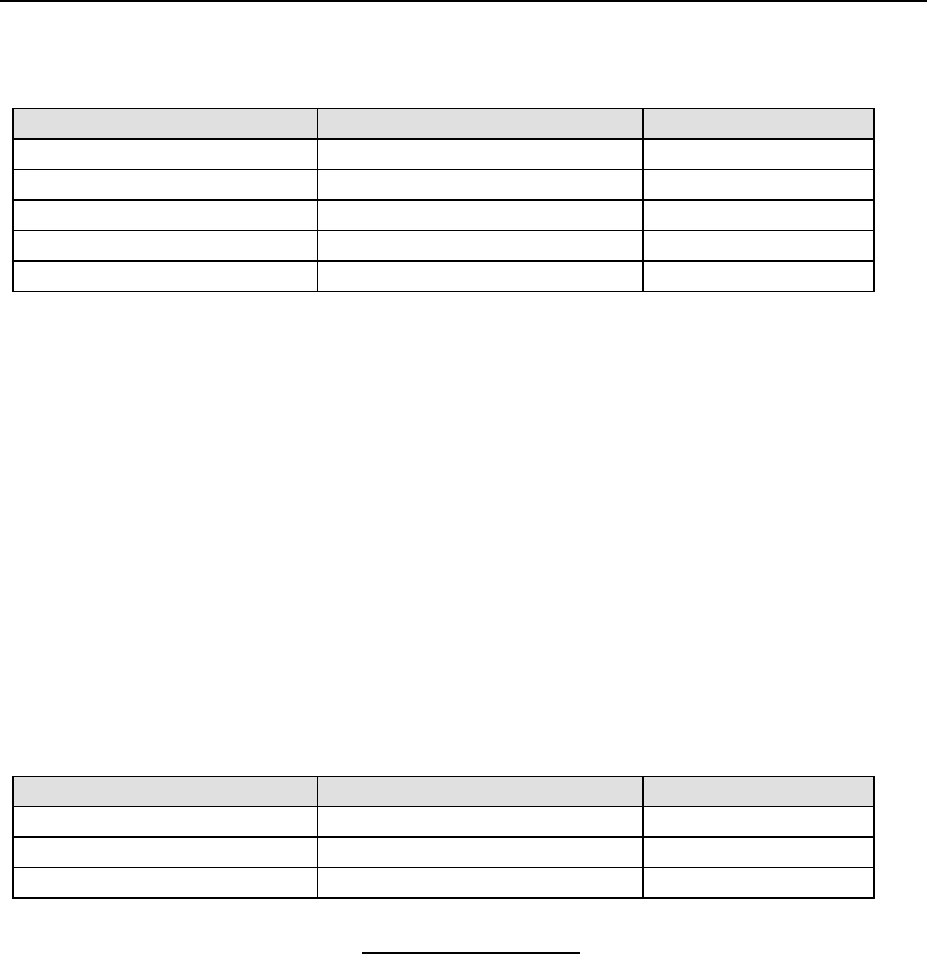
Data field names that can be translated
PCB data
Placement data
Component data
PCB ID *
1
Placement ID
Reference Designator
PCB size X *
2
Placement position X *
4
Component Comment
PCB size Y *
3
Placement position Y *
5
PCB layout offset X
Placement angle
PCB layout offset Y
Placement side *
6
*
1
PCB ID is extracted from the data file name by the Tango extension dll.
*
2
PCB size X is calculated by subtracting “PCB layout offset X” (6th field) from “Upper
Right X” (4th field).
PCB size X = “Upper right X” - PCB Layout Offset X
*
3
PCB size Y is calculated by subtracting “PCB layout offset Y” (7th field) from “Upper
Right Y” (5th field).
PCB size Y = “Upper right Y” - PCB Layout Offset Y
*
4
Placement position X is half the sum of “Lower Left X” (9th field) and “Upper Right X”
(11th field)
Placement position X = (“Lower Left X” + “Upper Right X”) / 2
*
5
Placement position Y is half the sum of “Lower Left Y” 109th field) and “Upper Right Y”
(12th field)
Placement position Y = (“Lower Left Y” + “Upper Right Y”) / 2
*
6
Placement side is located in the line starts with “PAD” keyword. The Placement side is
Top when the value is “TL;” Bottom when the value is “BL.”
●
Format definition
Data section
Section layout
Tag name
PCB data
Tag format
BOARD
Placement data
Tag format
C O MP, PA D
Component data Tag format COMP
A sample of "TANGO"
VERSION 1 3 A
BOARD 129 161 8065 4606 129 161
COMP "R53" "RES" "1K, .02%" "SMR1" "" 5504 1576 5448 1223 5630 1576 142 0
COMP "R52" "RES" "1K, .02%" "SMR1" "" 5864 1576 5824 1232 6006 1576 144 0
COMP "R40" "RES" "1K, .02%" "SMR1" "" 5681 1576 5638 1229 5820 1576 143 0
COMP "C43" "CAP" ".1MF" "CC0805" "" 4195 2578 4081 2450 4299 2632 41 0
COMP "C11" "CAP" ".001MF" "CC0805" "" 5325 2575 5297 2433 5444 2629 90 0
COMP "R39" "RES" "12" "RC0805" "" 5275 1975 5160 1821 5404 2029 43 0
COMP "C9" "CAP" ".1MF" "CC0805" "" 5050 2175 4919 2050 5154 2229 79 0
COMP "R55" "RES" "13K, .1%" "RC0805" "" 5050 1650 5022 1505 5179 1704 44 0
COMP "R49" "RES" "3.01K, .1%" "RC0805" "" 5050 1450 5022 1309 5179 1504 37 0
COMP "R54" "RES" "560" "RC0805" "" 4850 1450 4734 1298 4979 1504 42 0
COMP "R51" "RES" "10K, .1%" "RC0805" "" 4475 1650 4447 1514 4604 1704 40 0
COMP "R56" "RES" "12" "RC0805" "" 4225 1650 4197 1511 4354 1704 45 0
COMP "C30" "CAP" ".1MF, 100V" "CC0805" "" 4475 1450 4447 1319 4586 1504 108 0