FLEXLINE-CAD_INM.pdf - 第49页
44 BOC mark posit ion An expression to conver t the BOS mark position data into the st andard coordinate system is defined. Figur e 7.3.2 - 4 BOC M ark P ositio n 7.3.3 Cust om tran sformati on settin gs (placemen t) s…
43
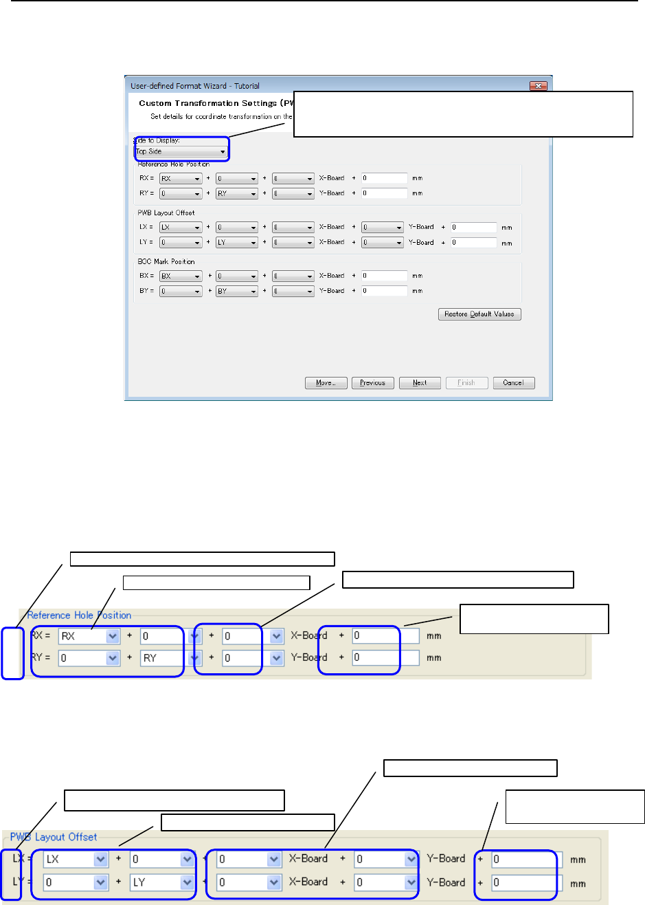
7.3.2 Custom transformation settings (PWB) screen
In coordinate transformation of the "Global Setup" screen, specify "Custom transformation"
and click the [Next] button. Then, the following screen is displayed.
Figure 7.3.2-1 Custom Transformation Settings (PWB)
* Click the "Restore Default Values" button to set the default values for all the values displayed
on the screen.
Reference hole position
An expression to convert the reference hole position data into the standard transformation
system is defined.
Figure 7.3.2-2 Reference hole position
PWB layout offset
An expression to convert the PWB layout offset data into the standard coordinate system is
defined.
Figure 7.3.2-3 PWB Layout Offset
From the pull-down menu, select this item and set each
of the top side and bottom side.
Reference hole position after transformation
Reference hole position of CAD data
PWB dimension increment/decrement value
Other increment/decrement
value
PWB layout offset of CAD data
PWB increment/decrement value
PWB layout offset after transformation
Other
increment/decrement
44
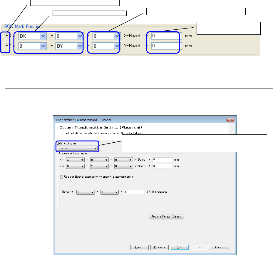
BOC mark position
An expression to convert the BOS mark position data into the standard coordinate system is
defined.
Figure 7.3.2-4 BOC Mark Position
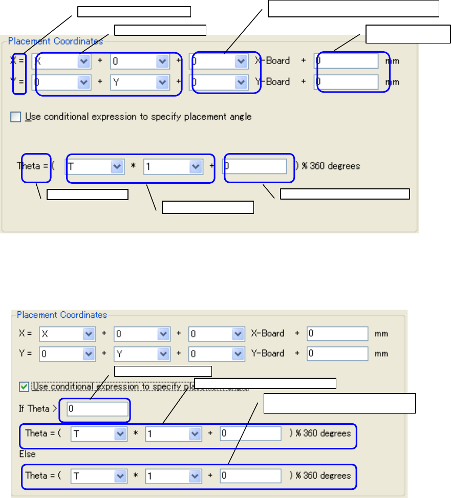
7.3.3 Custom transformation settings (placement) screen
In coordinate transformation of the "Global Setup" screen, specify "Custom transformation" and
click the button. Then, the "Custom transformation settings (placement)"screen is displayed.
Figure 7.3.3-1 Custom Transformation Settings (Placement)
* Click the "Restore Default Values" button to set the default values for all the values
displayed on the screen.
BOC mark position after transformation
BOS mark position of CAD data
PWB dimension increment/decrement value
Other increment/decrement
value
From the pull-down menu, select this item and set each
of the top side and bottom side.
45
An expression to convert the placement data into the standard coordinate system is defined.
Figure 7.3.3-2 Placement Coordinates
As one method of specifying the placement angle, a conditional expression can be set.
Check off "Use conditional expression to specify placement angle" to display the input screen
using the conditional expression.
Figure 7.3.3-3 Placement Coordinates (when using a conditional expression)
X and Y after transformation
X and Y of CAD data
PWB dimension increment/decrement value
Other
increment/decrement
θ after transformation
θ of CAD data
Other increment/decrement value
CAD data condition
Expression when the condition holds
Expression when the condition does not
hold