FLEXLINE-CAD_INM.pdf - 第65页
60 7.6.1 Definit ion of v alid/inv alid dat a T o convert only line 3 to line 5 ignoring line 1 and line 2 when the following data exists , set the lines containing "F" to Inv al id (or lines cont aining "…
59
7.6 Field translation screen
In each data item, the representation of CAD data must be matched to the settings in Flexline
CAD.
For example, when the placement side is defined, the top side and the bottom side are defined
as "T" and "B" respectively in the CAD data. However, because Flexline CAD does not know
whether the top side is "T" or "B", it is necessary to define that the top side is "T."
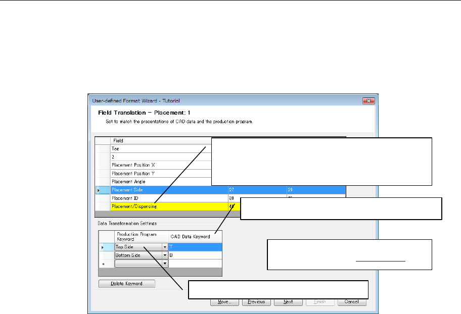
Figure 7.6-1 Field Translation defining method
* Regarding the field requiring field
translation, refer to "10.3 Field."
2. Select production program keyword.
1. Select the line (line of a yellow background) of the
field that requires field translation. Then, the
"data transformation settings" screen of the lower
column is displayed.
3. Enter the corresponding CAD data keyword.
60
7.6.1 Definition of valid/invalid data
To convert only line 3 to line 5 ignoring line 1 and line 2 when the following data exists, set the
lines containing "F" to Invalid (or lines containing "D" to Valid).
(1 1 "F" 1 -30908 307 0 0 0 0 0 "R1" "" "" "" "" 0 0 0 2 0 0 0 0 0 0 0 "" )
( 2 1 "F" 1 -3231 27734 0 0 0 0 0 "R1" "" "" "" "" 0 0 0 1 0 0 0 0 0 0 0 "" )
( 3 1 "D" 1 -30274 5385 5400 1 2 0 0 "F222" "" "" "" "" 0 0 0 0 0 0 0 0 0 0 0 "" )
( 4 1 "D" 2 -30783 3863 5400 1 2 0 0 "F05" "" "" "" "" 0 0 0 0 0 0 0 0 0 0 0 "" )
( 5 1 "D" 1 -29384 3352 5400 1 2 0 0 "F345" "" "" "" "" 0 0 0 0 0 0 0 0 0 0 0 "" )
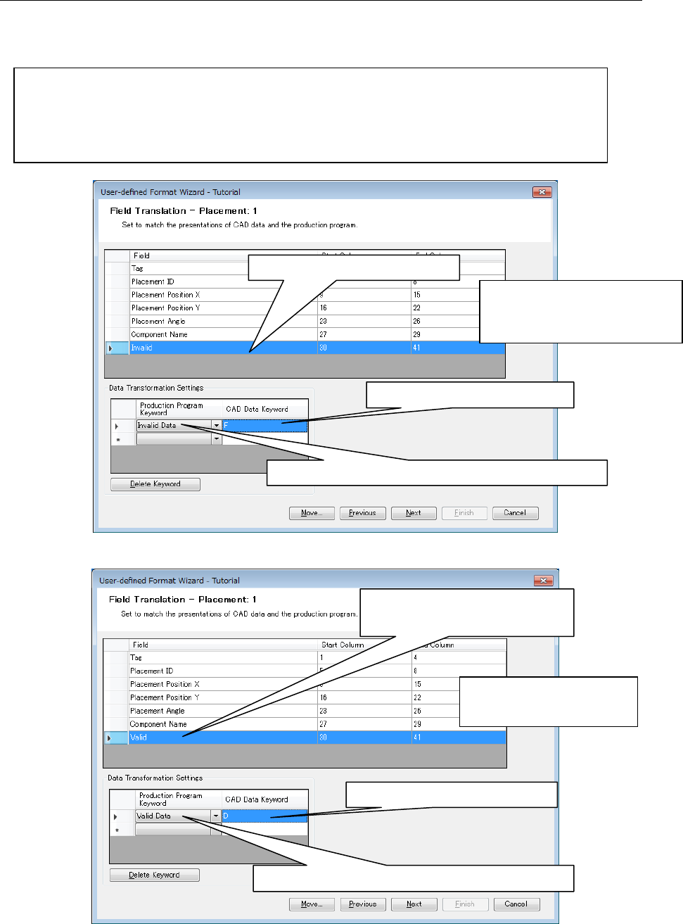
Figure 7.6.1-1 Field translation (Invalid Data setting)
Figure 7.6.1-2 Field Translation (Valid Data setting)
1. Select the line to set field.
3. Enter "F" in CAD Data Keyword.
2. Select "Invalid Data" in Production Program Keyword.
* When "Invalid Data" is defined,
not only "Invalid Data" fields
but also the whole line are not
converted.
1. Select the line to set field.
translation.
* In each section, up to 10
"Valid Data" and "Invalid
Data" can be defined.
3. Enter "D" in CAD Data Keyword.
2. Select "Valid data" in Production Program Keyword.
61
7.6.2 BOM (Bill of Material: Component Table)
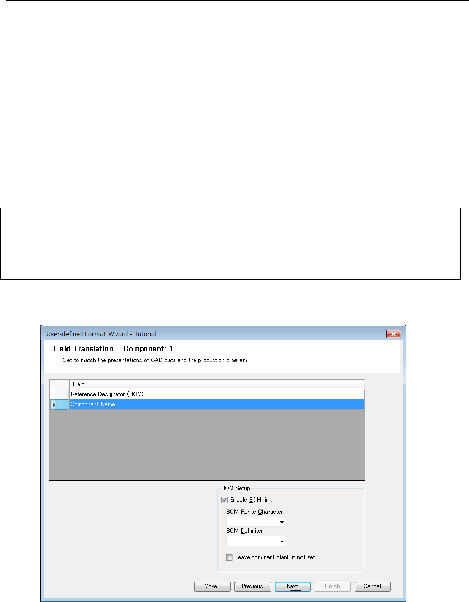
On the "Field translation" screen for component data, the "BOM settings" screen is displayed.
Check off "Enable BOM link" on the "BOM settings" screen. Then, when the same placement ID
is used for component data and placement data, the component name is copied to the
placement data.
In the case of "tutorial.txt", the placement data contains an placement ID but not any component
ID. Since the component data contains a placement ID, this component name is incorporated
into the placement data at transformation.
In "tutorial.txt", one placement ID is provided for one component name. In some cases,
however, multiple placement IDs may be provided for one component name. At this time, use
"BOM range character" and "BOM delimiter" are used as a specifying method.
When CAD data is defined as shown below, enter "-" into "BOM range character" and ";" into
"BOM delimiter."
Q1,"CAP 22PF, 5%, 50V(SMD1206)"
Q2,"74HCT241 (SMD SOL)"
U1-U9,"BC147" ←Component name of "BC147" for placement IDs of U1 to U9
C1;C4;C7-C11,"2N2886" ← Component name of "2N2886" for placement IDs of C1, C4, C7
to C11
"-" (hyphen), ":" (colon), "." (period) are available for BOM range characters.
"," (comma), ";" (semi-colon), and "/" (slash) are available for BOM delimiters.
Figure 7.6-2-1 Field Translation