FLEXLINE-CAD_INM.pdf - 第63页
58 7.5.5 Defi nition of IC mark 3 i n the placem ent sectio n The formats applicable to IC mark 3 are as follows: Even if data conv ersion is performed with the other format as an output format, IC mark 3 is not output. …
57
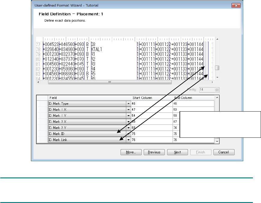
* When IC mark ID data exists in the input file, we recommend that the IC mark coordinate
data related to the IC mark ID should be in the same line and defined at the beginning of the
placement data. If only the mark ID exists in the subsequent data line, the mark coordinates
can be correctly converted even if no related IC mark coordinate data exists. This permits
saving the trouble of inputting every mark data at creation of mark data.
Figure 7.5.4-1 Definition of null IC mark ID and IC mark link
NOTE:
The IC mark ID field is not displayed in the data change dialog box.
(Example) Because no IC
mark ID and IC mark link data
are found in the input file, null
fields are defined.

58
7.5.5 Definition of IC mark 3 in the placement section
The formats applicable to IC mark 3 are as follows: Even if data conversion is performed with
the other format as an output format, IC mark 3 is not output. The IC mark 3 field is not
displayed in the data change dialog box.
• HLC Ver 6.0 to 12.0
• IS 2.00
• IS,IS Lite
• 2050 Ver 1.XX
• 2050R Ver 1.XX
• 2055R Ver 1.XX
• 2060 Ver 1.XX
• 2070 Ver 1.00/1.XX/2.1X
• 2060R Ver 1.XX
• 2080 Ver 1.00/1.XX/2.1X
• 2080R Ver 2.1X
• 3020 Ver 1.00
• 3020R Ver 1.00
• 3010 Ver 1.00
• 3020V Ver 1.00
• 3020VR Ver 1.00
• 3010A Ver 1.00
• 3020VA Ver 1.00
• 3020VRA Ver 1.00
• FX-1 Ver 1.XX
• FX-1R Ver 1.XX
• FX-2 Ver 1.00/1.XX
• FX-3 Ver 1.00/1.XX/3.50
• FX-3R Ver 4.XX
• FX-3RA Ver 1.00
• CX-1 Ver 1.00/1.XX
• RX-6 Ver1.00
• RX-6R Ver4.00
• RS-1 Vre1.00
• LC-01
NOTE:
Select the "IS, IS Lite" when you want to output in JaNets format.
59
7.6 Field translation screen
In each data item, the representation of CAD data must be matched to the settings in Flexline
CAD.
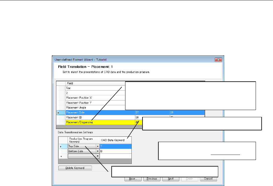
For example, when the placement side is defined, the top side and the bottom side are defined
as "T" and "B" respectively in the CAD data. However, because Flexline CAD does not know
whether the top side is "T" or "B", it is necessary to define that the top side is "T."
Figure 7.6-1 Field Translation defining method
* Regarding the field requiring field
translation, refer to "10.3 Field."
2. Select production program keyword.
1. Select the line (line of a yellow background) of the
field that requires field translation. Then, the
"data transformation settings" screen of the lower
column is displayed.
3. Enter the corresponding CAD data keyword.