FLEXLINE-CAD_INM.pdf - 第116页
A- 19 4. The circuit layout of f set and circuit out er dimensions of m atrix PW B are defined on the second PW B section definition screen. In the "Section Lay out", select "Line Range" and enter 16 …
A-18
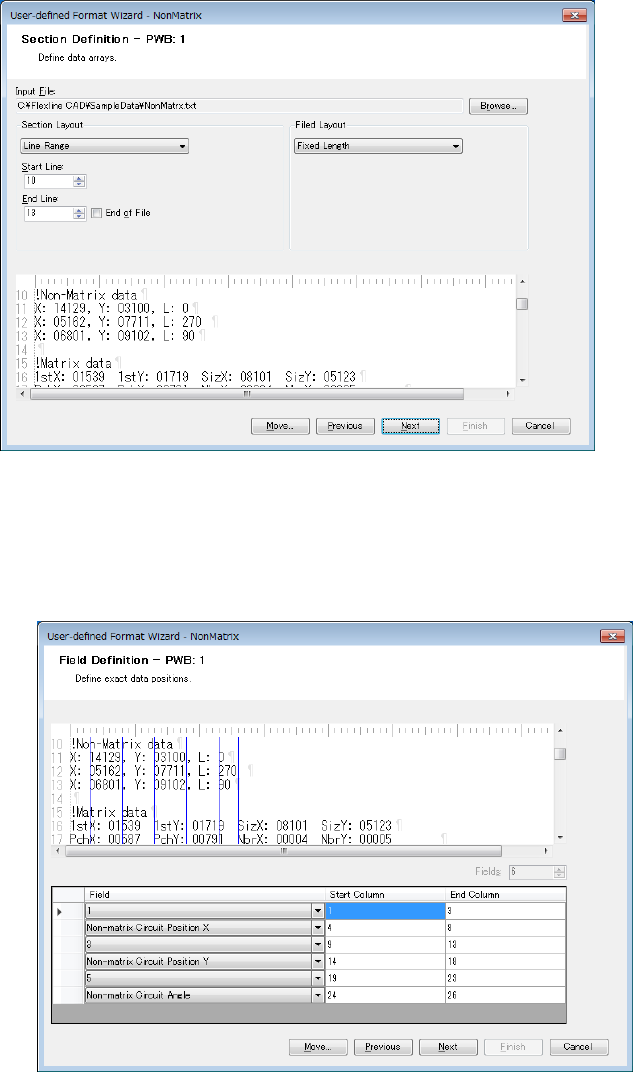
2. Read the file. In the "Section Layout", select the "Line Range" and enter 10 in the "Start
Line" and 13 in "End Line."
Figure A-29 Section Definition screen (PWB 1)
Click the "Next" button.
3. Set the "Non-matrix Circuit Position X", "Non-matrix Circuit Position Y", and Non-matrix
Circuit Angle."
Figure A-30 Field Definition screen (PWB 1)
When defining the circuit layout data, it is not possible to define other fields in the same
PWB section.
Click the "Next" button.
A-19
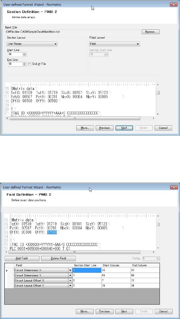
4. The circuit layout offset and circuit outer dimensions of matrix PWB are defined on the
second PWB section definition screen. In the "Section Layout", select "Line Range" and
enter 16 in the "Start Line" and 18 in "End Line." In the "Field Layout", select "Field."
Figure A-31 Section Definition screen (PWB 2)
Click the "Next" button.
5. Set the Circuit Layout Offset X, Circuit Layout Offset Y, and Circuit Dimensions X/Y. Set the
Circuit Layout Offset X, Circuit Layout Offset Y, and Circuit Dimensions X/Y.
Figure A-32 Field definition screen (PWB 2)
B-1
Appendix B Transformation
1. Definitions
CAD coordinate system: The coordinate system that a CAD package uses to
describe the orientation and location of integrated circuits
(ICs) on a PCB.
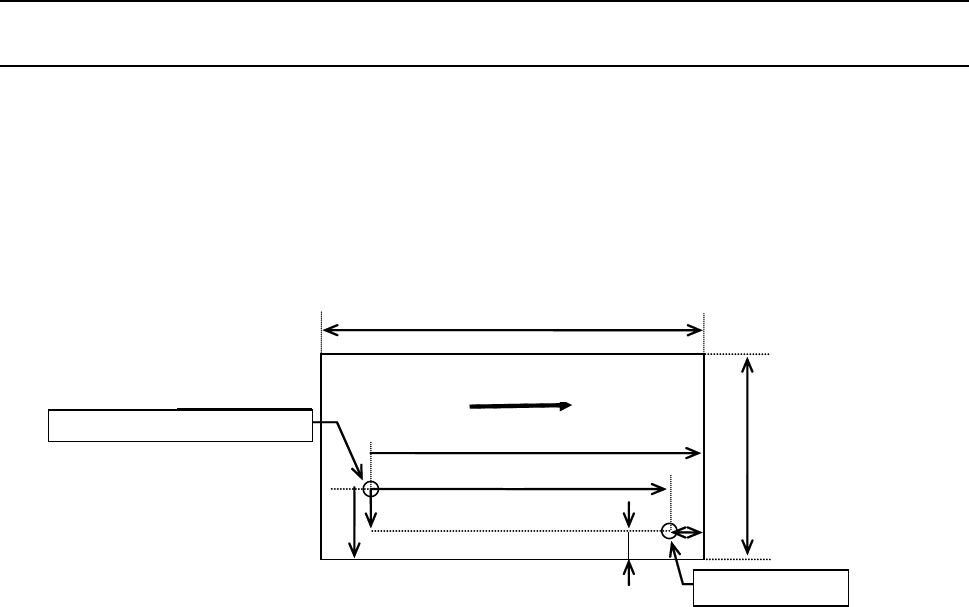
Flexline CAD coordinate system: The standard coordinate system as shown below:
In short, this is a coordinate system on the basis of the
transport direction from “Left to Right” of the Front reference.
Y
Front reference
X
Lx
Tx
Px
Ly
Ty
Py
Reference pin
Origin of
di t
Transport direction
Figure B-1 FlexlineCAD Coordinate System
Machine coordinate system: Four difference coordinate systems that any JUKI SMT
machine uses to reference and place ICs on a PCB, namely:
● Transport direction from “Left to Right” of the Front
reference
● Transport direction from “Right to Left” of the Front
reference
● Transport direction from “Left to Right” of the Rear
reference
● Transport direction from “Right to Left” of the Rear
reference
Right-hand rotation rule: Counterclockwise angles are positive and clockwise angles
are negative.
Right-angle coordinate system: The angle between any two of the X, Y, and Z coordinate
axes = 90°.
Reference hole coordinates
Reference hole
Transport direction