FLEXLINE-CAD_INM.pdf - 第50页
45 An expression to conver t the placement data into t he standard coor dinate system is defined. Figur e 7.3.3 - 2 Placement C oordinates As one method of specifying the placement angle, a conditional expression can be …
44
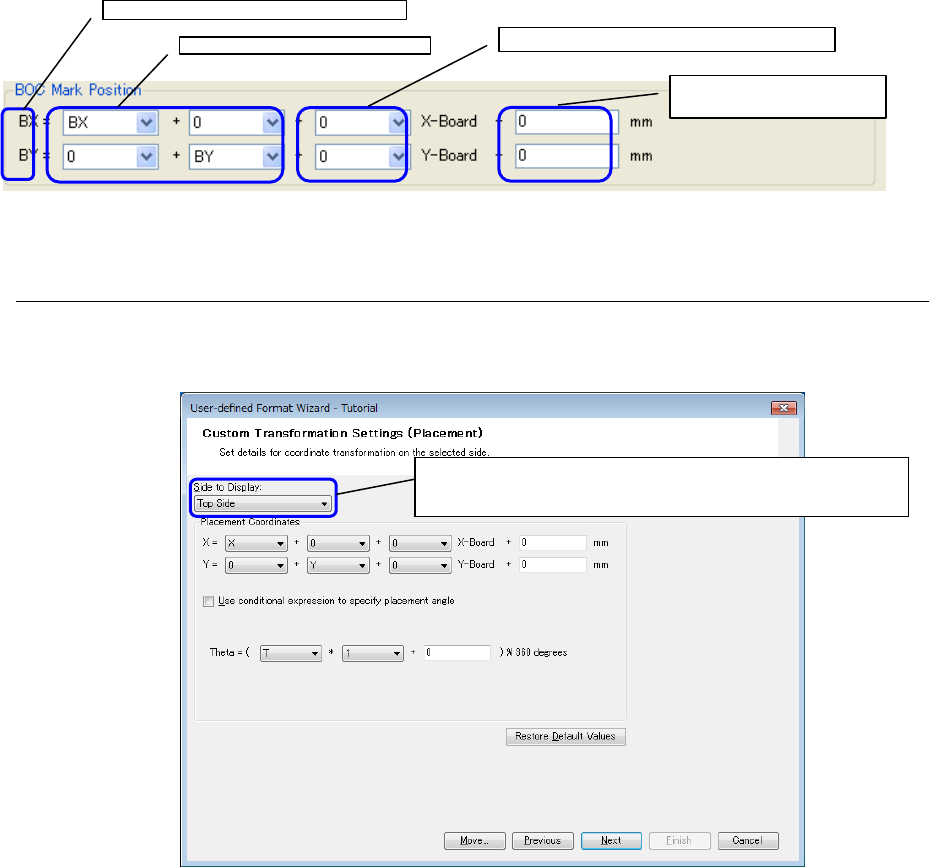
BOC mark position
An expression to convert the BOS mark position data into the standard coordinate system is
defined.
Figure 7.3.2-4 BOC Mark Position
7.3.3 Custom transformation settings (placement) screen
In coordinate transformation of the "Global Setup" screen, specify "Custom transformation" and
click the button. Then, the "Custom transformation settings (placement)"screen is displayed.
Figure 7.3.3-1 Custom Transformation Settings (Placement)
* Click the "Restore Default Values" button to set the default values for all the values
displayed on the screen.
BOC mark position after transformation
BOS mark position of CAD data
PWB dimension increment/decrement value
Other increment/decrement
value
From the pull-down menu, select this item and set each
of the top side and bottom side.
45
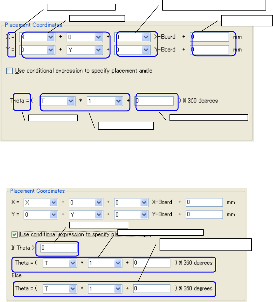
An expression to convert the placement data into the standard coordinate system is defined.
Figure 7.3.3-2 Placement Coordinates
As one method of specifying the placement angle, a conditional expression can be set.
Check off "Use conditional expression to specify placement angle" to display the input screen
using the conditional expression.
Figure 7.3.3-3 Placement Coordinates (when using a conditional expression)
X and Y after transformation
X and Y of CAD data
PWB dimension increment/decrement value
Other
increment/decrement
θ after transformation
θ of CAD data
Other increment/decrement value
CAD data condition
Expression when the condition holds
Expression when the condition does not
hold
46
<Exercise 1>
* Try to make a calculation on the supposition of X coordinate = 50, Y coordinate = 35, PWB
dimension X = 300, and PWB dimension Y = 200.
In the case of X = [X] + [0] + [0]X - Board + [0], the X value after transformation is 50.
In the case of X = [X] + [0] + [1]X - Board + [0], the X value after transformation is 350.
In the case of X = [0] + [Y] + [0]X - Board + [0], the X value after transformation is 35.
In the case of X = [X] + [0] + [-1]X - Board + [0], the X value after transformation is -250.
In the case of X = [X] + [0] + [0]X - Board + [10], the X value after transformation is 60.
In the case of Y = [0] + [Y] + [0]Y - Board + [0], the Y value after transformation is 35.
In the case of Y = [0] + [Y] + [1]Y - Board + [0], the Y value after transformation is 235.
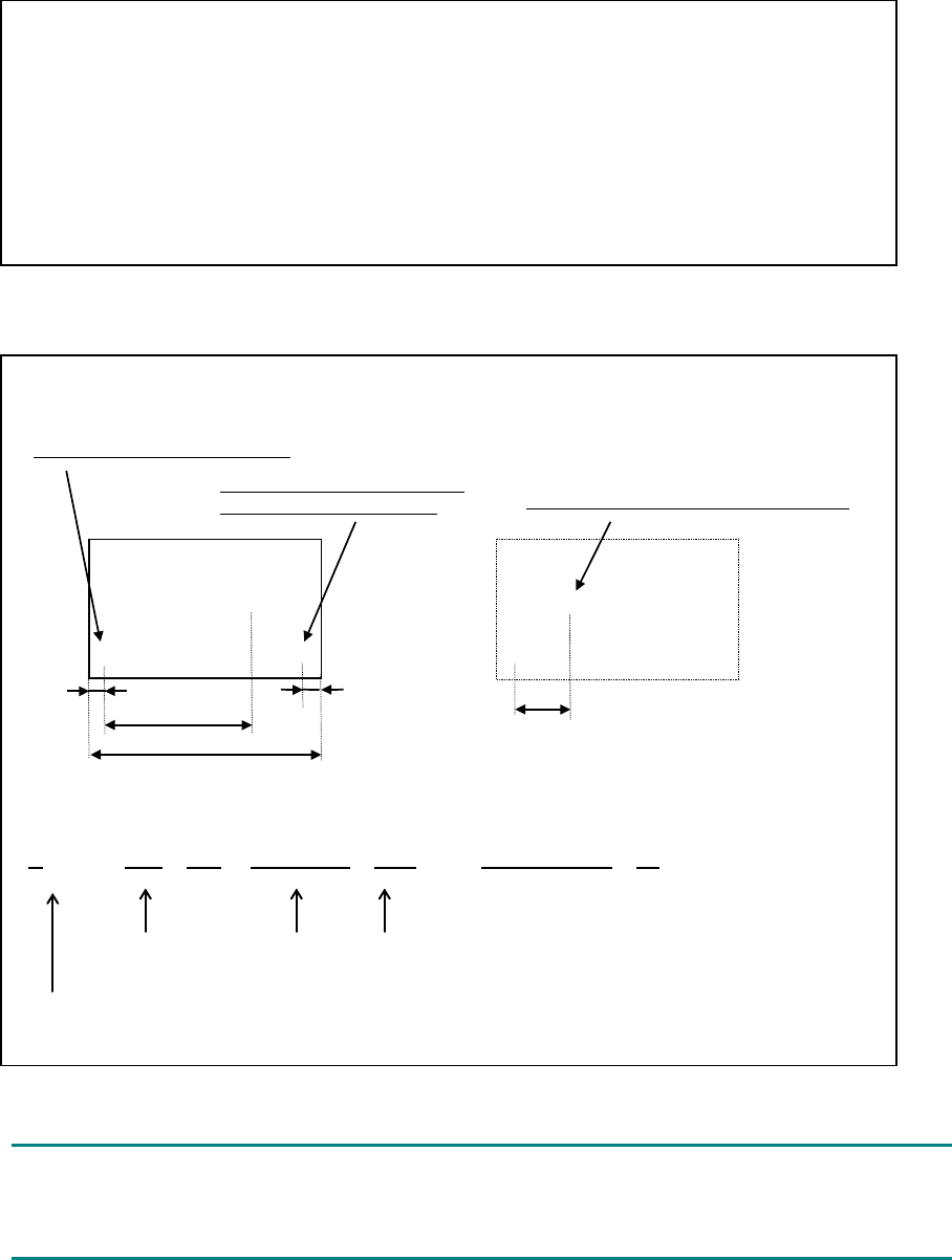
<Exercise 2>
* The bottom-side placement coordinates are defined in the coordinate system viewed from
the top side as shown in the following figure, transformation is required.
Origin as viewed from the top side
●
●
◎
◎
◎
5
5
95
45
150
This point becomes an origin as
viewed from the bottom side.
Consequently, it becomes as shown below.
At this time, the expression is as follows:.
X = [-X] + [0] + [1]X-Board + [-10] = -95+0+150-10 = 45
When converting the placement data, it is defined that numeric data should be converted by
user-defined wizard but no data exists in the file to be actually converted. In this case, 0 is set
as the default value in the field of the output file.
Length from the end face of PWB to the
former origin (5) + Length from the end face
to the new origin (5)
X coordinates after
transformation
CAD
coordinates
PWB outer
dimensions