FLEXLINE-CAD_INM.pdf - 第117页
B-1 A ppendix B T ransformation 1. Defini tions CAD coordinate sy stem: The coordinate syst em that a CAD package uses to describe the orient ation and l ocation of integrated circuit s (ICs) on a PCB. Flexline CAD coord…
A-19
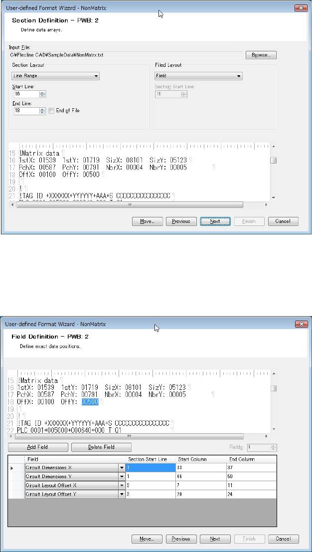
4. The circuit layout offset and circuit outer dimensions of matrix PWB are defined on the
second PWB section definition screen. In the "Section Layout", select "Line Range" and
enter 16 in the "Start Line" and 18 in "End Line." In the "Field Layout", select "Field."
Figure A-31 Section Definition screen (PWB 2)
Click the "Next" button.
5. Set the Circuit Layout Offset X, Circuit Layout Offset Y, and Circuit Dimensions X/Y. Set the
Circuit Layout Offset X, Circuit Layout Offset Y, and Circuit Dimensions X/Y.
Figure A-32 Field definition screen (PWB 2)
B-1
Appendix B Transformation
1. Definitions
CAD coordinate system: The coordinate system that a CAD package uses to
describe the orientation and location of integrated circuits
(ICs) on a PCB.
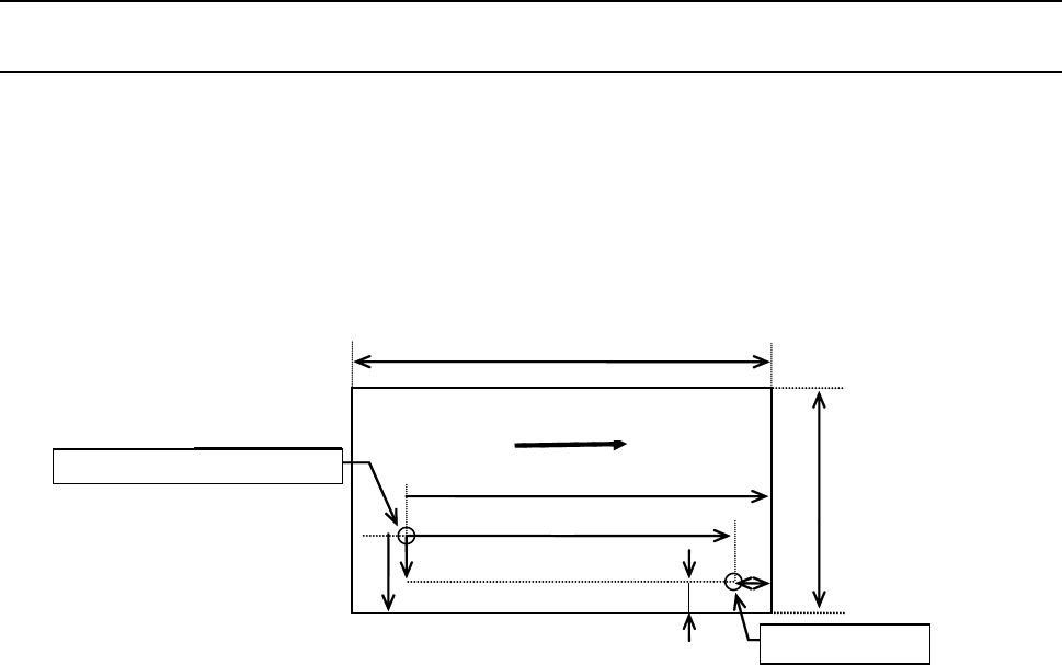
Flexline CAD coordinate system: The standard coordinate system as shown below:
In short, this is a coordinate system on the basis of the
transport direction from “Left to Right” of the Front reference.
Y
Front reference
X
Lx
Tx
Px
Ly
Ty
Py
Reference pin
Origin of
di t
Transport direction
Figure B-1 FlexlineCAD Coordinate System
Machine coordinate system: Four difference coordinate systems that any JUKI SMT
machine uses to reference and place ICs on a PCB, namely:
● Transport direction from “Left to Right” of the Front
reference
● Transport direction from “Right to Left” of the Front
reference
● Transport direction from “Left to Right” of the Rear
reference
● Transport direction from “Right to Left” of the Rear
reference
Right-hand rotation rule: Counterclockwise angles are positive and clockwise angles
are negative.
Right-angle coordinate system: The angle between any two of the X, Y, and Z coordinate
axes = 90°.
Reference hole coordinates
Reference hole
Transport direction

B-2
2. Overview
Computer Aided Design (CAD) software packages use different coordinate systems to describe
the location and orientation of components (ICs) placed on a PCB. On the other hand, JUKI's
SMT machines use the said four systems in the transport direction. The PCB reference
coordinate is interpreted by the PCB transport reference (Front, or Rear) and PCB transport
direction (“Right to Left,” or “Left to Right”). Thus, the need for geometric transformation
between coordinate systems is significant.
Flexline CAD provides a mechanism to transform both top and bottom CAD coordinate system
to the Flexline CAD coordinate system. Furthermore, Flexline CAD can transform from Flexline
CAD coordinate system to any of the four possible machine coordinate systems. As a result of
the two-stage transformation (CAD coordinate system / Flexline CAD coordinate system then
Flexline CAD coordinate system / machine coordinate system), Flexline CAD is capable of
transforming any CAD coordinate system to any of the machine coordinate systems. This
document describes the techniques that Flexline CAD adapts in transforming between different
coordinate systems.
3. Transforming CAD coordinate system to machine coordinate system
CAD coordinate system transforms to the Flexline CAD coordinate system, then Flexline CAD
coordinate system transforms to machine coordinate system.
3.1 Transforming CAD coordinate system to Flexline CAD coordinate system
Transforming CAD coordinate system to Flexline CAD coordinate system is implemented by
taking the following two operation steps:
1. Unit conversion
When each of the CAD coordinate system and the Flexline CAD coordinate system uses a
different unit system related to dimensions and angle, unit conversion is executed.
2. CAD top PCB perspective \ Flexline CAD coordinate system or CAD bottom PCB
perspective \ Flexline CAD coordinate system
Flipping the X-axis around the Y-axis is a transformation that produces a mirror image of the
X-axis about the Y-axis. Flipping the Y-axis around the X-axis is a transformation that
produces a mirror image of the Y-axis about the X-axis.
Translating CAD coordinate system is done by repositioning its origin point along a straight
line path from one coordinate location to another by adding the translation distance.
However, Flexline CAD uses the origin point of Flexline CAD coordinate system ((0, 0) point
of Flexline CAD coordinate system) to be the destination point of translation.
The following two equations transform (X, Y) point to (X', Y') where (c, b) is a translation
distance from the CAD coordinate system to the Flexline CAD coordinate system.
(Ox, Oy): Offset point.
a = 0, +1 or -1. b = 0, +1 or -1.
% is a remainder, and
θ ′ is the angle of rotation for the top components.
X ′ = a X + b Y + (X+ OX)
Y
′ = b X + a Y + (Y+ OY)
θ ′ = (k θ + j 360 °) % 360 °