FLEXLINE-CAD_INM.pdf - 第44页
39 • [ Extension ] S pecify extensions for the CAD data file. Only the ext ensions specified here are displayed in the file list. For the extensions that are displayed in the extension list, refer t o "10.2 Data fi …
38
7.2 Global setup screen *1
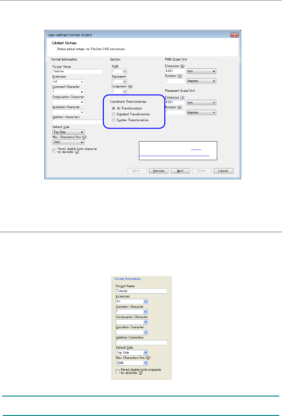
First, the "Global Setup" screen is displayed.
Figure 7.2-1 User-defined Format Wizard (Global Setup)
*1 The screen displayed with the Version 5.10 or earlier is different from that with the Version
6.00 or later.
7.2.1 Format information
Enter the format name.
The characters available for the format name are alphanumeric characters, underline symbol
(_), and hyphen (−).
Regarding the other items (options), enter data as required.
Figure 7.2.1-1 Format Information
Note: In every character input field, optional characters can be entered in addition to the
characters indicated in the list.
Refer to the section "7.3
Coordinate transformation."

39
•
[Extension]
Specify extensions for the CAD data file.
Only the extensions specified here are displayed in the file list.
For the extensions that are displayed in the extension list, refer to "10.2 Data file
extensions."
•
[Comment Character]
This character is used for lines to be ignored, such as data comment lines.
When the characters selected here are at the beginning of the line, this line is ignored to
continue the processing.
If the comment character is specified as "!" when the CAD data is as mentioned below, line
1, line 6, and line 7 will be ignored.
* In the character list, ";" (semi-colon), "//" (forward dash), "!" (exclamation mark), and " ' "
(apostrophe) are displayed.
•
[Continuation Character]
This character is used to handle multiple lines as a single line. If symbol specified here is
attached to the end, the next line is handled as the same line.
* In the character list, "_" (under-score), "\" (Backslash (Yen mark)), "/" (slash) are
displayed.
•
[Quotation Character]
Specify the character (first character and last character only) to be ignored.
In the following case, if """ is specified as quotation mark, the component names after
conversion are "SOT23", "QFP200P0.3", "PLCC84" without """.
* In the character list, """ (quotation mark) and "{}" (bracket) are displayed.
* The data in the quotation mark is converted as a single field.
Tag X-
coordinate
Y-
coordinate
Angle
Component name
before conversion
!Flexline CAD Tutorial
Flexline CAD Tutorial PWB
150000 100000
150000 000000
10000 10000 145000 95000
!
!TAG ID +XXXXXX+YYYYYY+AAA+S CCCCCCCCCCCCCCCC
PLC_0001+005000+000640+000 T Q1
PLC_0002+004350+001230+090 T Q2
!TAG ID +XXXXXX+YYYYYY+AAA+S CCCCCCCCCCCCCCCC
PLC_0001+005000+000640+000 T “SOT23”
PLC_0002+004350+001230+090 T “QFP200P0.3”
PLC_0003+032560+023440+000 T “PLCC84”
↑ ↑ ↑ ↑ ↑
40
•
[Deletion Character]
When any unnecessary character is attached to the numeric value of "X", "Y", or "Angle" of
placement data, this character can be deleted by specifying it.
For example, when the value of X coordinates is "X1234", [X] will be ignored at conversion
if "X" is entered in advance.
However, note that the deletion character must be the first or last character of the character
string. ("X1234" and "1234X" can be recognized but "1X234" cannot be recognized.)
Enter the deletion character by putting it in """ like ""XY"".
For example, when "X", "Y", and "A" are deletion characters, enter ""XYA"" (including the
double quotation mark). Flexline CAD deletes a blank regardless of whether the deletion
character is specified or not.
* The deletion character is valid for the "X", "Y", and "Angle" fields of placement data.
•
[Default Side]
When no PWB surface is specified in the placement record, the default side is used. For
the default side, select "top side" or "bottom side."
•
[Max. Characters/line]
Set the maximum number of characters per line in the input format. Select one of "2048",
"3072", and "4096."
•
[Permit double-byte character for delimiter]
Check off this item when a double-byte character is included in the delimiter in the field
definition of the input format. When this item is not checked off, only a single-byte character
is used as the delimiter.
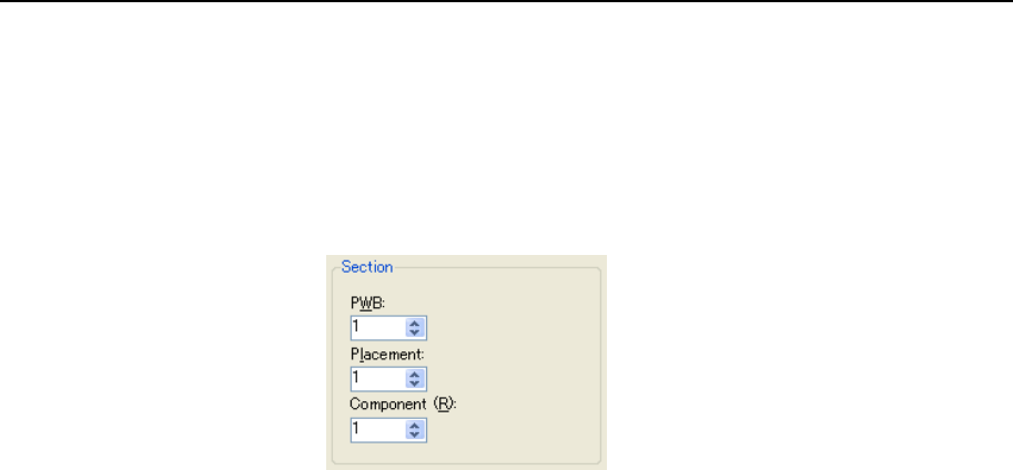
7.2.2 Section
In this field, set the target data for conversion out of PWB data, placement data, and component
data. Enter the number of sections (number of data group to be defined) of each data. The
settable number of sections is 0 to 30 for PWB data, and 0 to 1 for placement data and
component data. Accordingly, only one section can be defined for placement data and
component data.
If a larger number of sections than 1 is specified for PWB data, the PWB section definition
screen of the set number is displayed.
Figure 7.2.2-1 Section
•
For multi-circuit matrix or multi-circuit non-matrix conversion, it is necessary to define the
PWB configuration field. (If this field is not defined, single-circuit matrix conversion is
performed.)
•
For defining the BOC mark position, the BOC type field must be defined. For defining the
bad mark position, the mark type must be defined.