FLEXLINE-CAD_INM.pdf - 第109页
A- 12 7. Component Se ction Next, the screen t o define component data is displayed. In the placement dat a of "T utorial.txt", there is no "Component name." However , "T utorial.txt" correl…
A-11
6.2.2 Defining the field
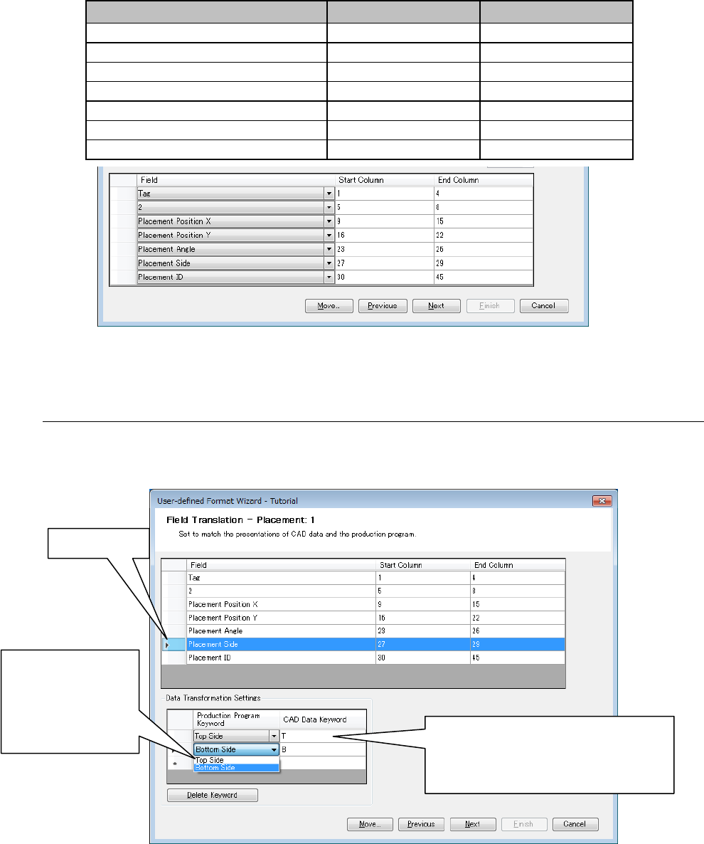
Next, each of these fields must be correlated so that Flexline CAD can recognize it. Click the
cell of a field and select the field from the displayed list.
In this example, the fields are as shown below:
Field
Start column
End column
Tag
1
4
(Does not need to be defined)
5
8
Placement position X
9
15
Placement position Y
16
22
Placement angle
23
26
Placement side
27
29
Placement ID
30
45
Figure A-14 Placement data fields
6.3 Field Translation screen (definition of placement side)
In the placement data of CAD data, the placement side is distinguished between T" and "B."
Now, define the "T" as the top side and "B" as the bottom side.
Figure A-15 Field Translation screen
Click the "Next" button.
①
Click here.
②
Click the cell of
"Production
program
keyword" and
select "Top
side."
③
Enter the "T" in the cell of "CAD data
keyword." Likewise, for the lower
column, select "Bottom side" in
②
and enter the "B."
A-12
7. Component Section
Next, the screen to define component data is displayed.
In the placement data of "Tutorial.txt", there is no "Component name."
However, "Tutorial.txt" correlates the placement ID and the component name in the component
data. The component name (component name linked with the placement ID) is converted by
this setting.
* Though there are component names exceeding 20 characters, transformation is performed
without editing.
7.1 Section definition screen
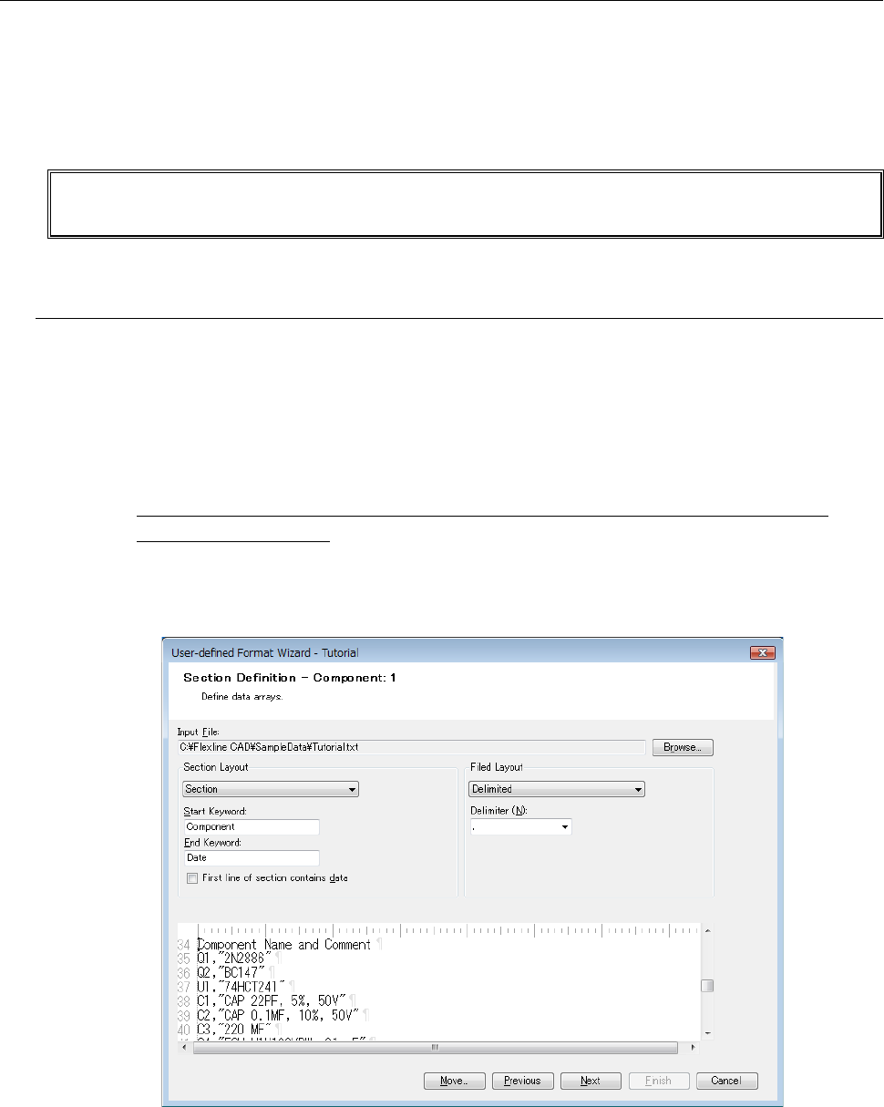
Move the "scroll bar" provided on the right side of "File display" downward by clicking. Then, the
component data screen is displayed.
● Section layout
From the list of "Section Layout", select the "Section" and enter "Component" in "Start
Keyword" and "Date" in "End Keyword."
* Enter them in the keywords by distinguishing between upper-case characters and
lower-case characters.
● Field layout
From the list of "Field Layout," select the "Delimited", and from the list of Delimiter," select ",."
Figure A-16 Section Definition screen (Component)
Click the "Next" button.
A-13
7.2 Field definition screen
Next, specify the actual field position and define a field.
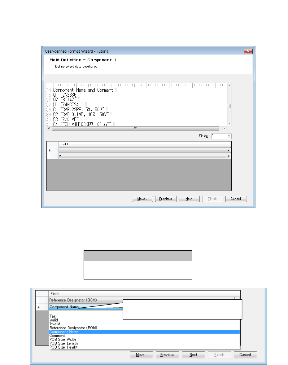
7.2.1 Specifying the number of fields
Enter "2" as the number of fields in the "Field" text box and press the Enter key.
Figure A-17 Field Definition screen (Component)
7.2.2 Defining a field
Next, define a field. Click the cell of a field, and select the field from the displayed list.
Field
Reference designator (BOM)
Component name
Figure A-18 Component data field
Click here to display a list and select a field
from the list displayed by pulling down.