FLEXLINE-CAD_INM.pdf - 第60页
55 7.5.4 Defi nition of IC mark I D at the p lacement sect ion The formats applicable to the IC mark ID are as follows : Even if dat a conversion is performed with the other formats as an output format, no IC mark ID is …
54
7.5.2 Delimited
This is a defining method for the case where the each item of the field is separated by delimiter.
Figure 7.5.2-1 Field definition (delimiter)
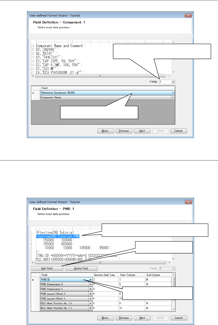
7.5.3 Field
This is a defining method when the data has no regularity. Each item of data can be defined
optionally.
◊ On the section start line, the number of lines counted from the section start line set at the
field layout is displayed.
Figure 7.5.3-1 Field definition (field)
1. Enter the number of fields to be defined in
Fields and press the "Enter" key.
2. Select the target field name to be
defined.
1. Select the character string to be defined as the
field by mouse.
2. Click the "Add field"
button.
3. Select the target field name to
be defined.

55
7.5.4 Definition of IC mark ID at the placement section
The formats applicable to the IC mark ID are as follows: Even if data conversion is performed
with the other formats as an output format, no IC mark ID is output.
• HLC Ver 5.4 to 12.0
• IS 2.00
• IS,IS Lite
• 2010 Ver 2.00
• 2020 Ver 2.00
• 2030 Ver 2.00
• 2040 Ver 2.00
• 2050 Ver 1.XX
• 2050R Ver 1.XX
• 2055R Ver 1.XX
• 2060 Ver 1.XX
• 2060R Ver 1.XX
• 2070 Ver 1.00/1.XX/2.1X
• 2080 Ver 1.00/1.XX/2.1X
• 2080R Ver 2.1X
• 3020 Ver 1.00
• 3020R Ver 1.00
• 3010 Ver 1.00
• 3020V Ver 1.00
• 3020VR Ver 1.00
• 3010A Ver 1.00
• 3020VA Ver 1.00
• 3020VRA Ver 1.00
• FX-1 Ver 1.XX
• FX-1R Ver 1.XX
• FX-2 Ver 1.00/1.XX
• FX-3 Ver 1.00/1.XX/3.50
• FX-3R Ver 4.XX
• FX-3RA Ver 1.00
• CX-1 Ver 1.00/1.XX
• RX-6 Ver1.00
• RX-6R Ver4.00
• RS-1 Ver1.00
• LC-01
To convert the IC mark coordinate data with the above formats as output formats, be sure to
define the three fields of IC mark ID, IC mark type, and IC mark link by placement section.
When these data are not found in the input file, the contents of definition are blank. However, be
sure to define the field. The IC mark ID is automatically created for the output file.
NOTE:
Select the "IS, IS Lite" when you want to output in JaNets format.

56
To convert the IC mark coordinates into any output format other than the above, it is not
necessary to define the IC mark ID, IC mark type, and IC mark link.
The following is a data example of IC mark ID and IC mark coordinates provided in the
placement data section.
PLA ID
PLA Pos X
PLA Pos Y
PLA Angle
PLA Link ID
MARK Use
MARK Link
MARK ID MARK 1X MARK 1Y
MARK 2X MARK 2Y
1 0.11 0.22 0
Q1 Y
M001 11.11 11.22 11.33 11.44
2 11.11 11.22
90 R2
Y
Mark Two 22.11 22.22 22.33 22.44
3 22.11
22.22 180 D2 Y
Third Mark
33.11 33.22 33.33 33.44
4
33.11 33.22 270 UY Y Mark IV 44.11 44.22
44.33 44.44
5 44.11 44.22 180 BX Y MK V 55.11
55.22
55.33 55.44
6 55.11 55.22 90 VD
N
7 66.11 66.22 0
ZZ Y Mark Two
8 77.11
77.22
270 TO Y M001
9
88.11
88.22 180 P1 Y MK V
10 99.11 99.22 90 C3 Y Mark Two
11 110.11 110.22 0 PO
Y Third Mark
12 121.11 121.22
270 R5
N
13 132.11
132.22 90
D4
Y Mark IV
14 143.11 143.22 0 TH Y Third Mark
15 154.11 154.22 0 X1 Y Third Mark
16 165.11 165.22 90 13 Y
Mark Two
17 176.11 176.22 180
80 Y
Mark IV
18 187.11 187.22
180
PR Y M001
19 198.11
198.22
0 IS N
20 209.11 209.22 90 SA Y Mark IV
21 220.11 220.22 270 SA Y Mark IV
22 231.11 231.22 180 GI
N
23 242.11 242.22
0
RI Y Mark Two
24 253.11 253.22 0 BG Y MK V
25 264.11 264.22 90 C2 Y Mark IV