FLEXLINE-CAD_INM.pdf - 第71页
66 Chapter 8 Dat a modification dialog box *1 Before data is output , it can be edited. Regarding three sections (PW B data, placement data, and component dat a), data items can be modified. PW B data items that are not …
65
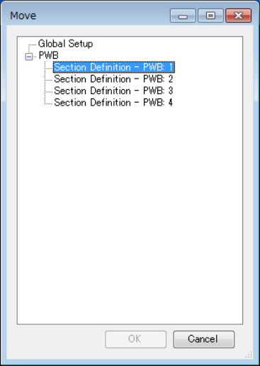
Figure 7.8.3-2
“Move” dialog box displayed
if any of the screens is not set up completely
When you increase the number of PWBs on the “Global Setup” screen, it is also supposed
that there is a screen whose setting is not made completely. For example, if you perform the
following operations, the PWB “5” is not set up completely in Step 5, and you cannot move to
any of the screens: “PWB 5,” “Placement” and “Component.” In this case, the screen
described above appears also.
1 Specify “4” in the “PWB” field, “1” in the “Placement” field, and “1” in the “Component” field
on the “Global Setup” screen.
2 Click the “Next” button on the “Field Translation – Component” screen to display the “User-
defined Format Wizard finishes” screen.
3 Display the “Move” dialog box on the “User-defined Format Wizard finishes” screen, and
then move to the “Global Setup” screen.
4 Change the setting of the “PWB” field to “5” on the “Global Setup” screen.
5 Display the “Move” dialog box on the “Global Setup” screen.
66
Chapter 8 Data modification dialog box *1
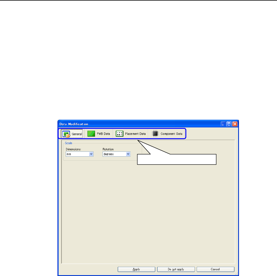
Before data is output, it can be edited.
Regarding three sections (PWB data, placement data, and component data), data items can be
modified. PWB data items that are not provided in the input file can also be added. For
placement data and component data, however, only modification can be performed but addition
cannot be performed.
* Data editing and addition can also be performed by machine, The production support
system after CAD conversion. Accordingly, the data modification dialog box is not always
required.
* The display/on-splay of the data modification dialog box is set in Environment settings. For
how to display the data modification dialog box, refer to "9.1.3 Conversion setting screen."
After conversion is started, the data modification dialog box is displayed during conversion
when the display of the data modification dialog box is set.
Figure 8-1 Data modification dialog box
*1 The screen displayed with the Version 5.10 or earlier is different from that with the Version
6.00 or later.
Click it to switch the display data.
67
8.1 General
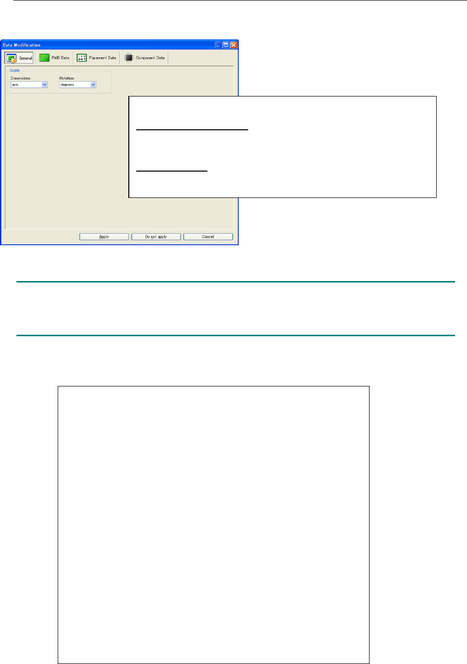
When the data modification dialog box is displayed, the general screen is displayed in the first
place.
Figure 8.1-1 General
NOTE:
After the display unit is changed in the data modification dialog box, the data is recalculated.
Note that the data accuracy may be somewhat lost depending on the source data.
The coefficients of conversion used in Flexline CAD are as follows:
<Unit change of the data displayed in the data modification dialog box>
Initial value of display unit: It is the unit set in input format when value
set in "Change" - "Unit of default" in environment setup is "Auto".
It is the unit when setting value is things except "Auto".
JUKI type format: Dimension "mm" and rotation "degrees"
At the end of the data modification dialog box, the units of all the data
are recalculated in "mm" for dimension and "degrees" for rotation.
1 Inch = 1000 mils
1 Inch = 25.4 mm
1 Inch = 2540 (x) 1/100 mm
1 Inch = 2.54 cm
1 mil = 0.001 inches
1 mil = 0.0254 mm
1 mil = 2.54 (x) 1/100 mm
1 mil = 2.54 / 1000 cm
1 mm = 3.93700287401576E-02 inches
1 mm = 39.3700787401575 mils
1 mm = 100 (x) 1/100 mm
1 mm = 1 / 10 cm
1/100 mm = 3.93700287401576E-04 inches
1/100 mm = 0.393700787401575 mils
1/100 mm = 1 / 100 mm
1/100 mm = 1 / 1000 cm
1 cm = 1 / 2.54 inches
1 cm = 1000 / 2.54 mils
1 cm = 10 mm
1 cm = 1000 (x) 1/100 mm