FLEXLINE-CAD_INM.pdf - 第38页
33 Displaying Input File Select the line header of the line to be displayed. The selected line color is reversed. Figure 6. 2 - 7 Selecting a fi le After specifying the line to be display ed, execute one of the following…
32
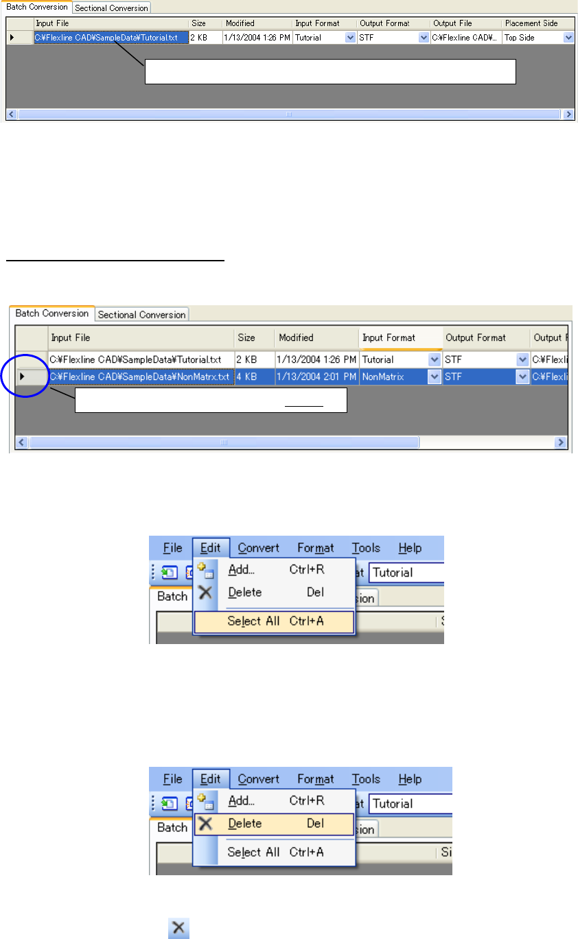
Figure 6.2-3 Batch conversion file table after an input file is added
* From Windows Explorer, drag and drop the file into the file table to add the input file to the file
table. (To drag and drop a file under Windows Vista or later OS, you have to prohibit Flexline
CAD from being executed with administrator’s privileges or execute Windows Explorer with
administrator’s privileges.)
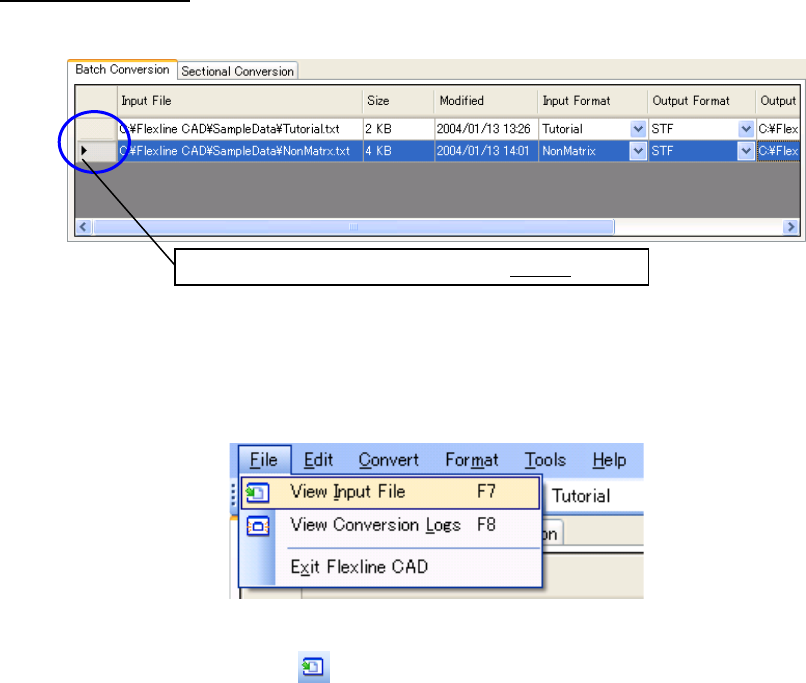
Deleting a file from the file table
Select the line header of the line to be deleted in the file table. The selected line color is
reversed.
Figure 6.2-4 File selection
For deleting all the files from the file table, select all the lines of the file table by clicking the
"Edit" - "Select all" command.
Figure 6.2-5 "Edit" - "Select all" menu
After specifying the line to be deleted, execute either one of the following operations of (1) and
(2).
(1) Select the "Edit" - "Delete" menu.
Figure 6.2-6 "Edit" "Delete" menu
(2) Click the "Delete" ( ) of the tool bar.
A delete confirmation message is displayed. Then, click the [OK] button.
File information is added to the batch conversion file table.
Select the line to be deleted by this header
33
Displaying Input File
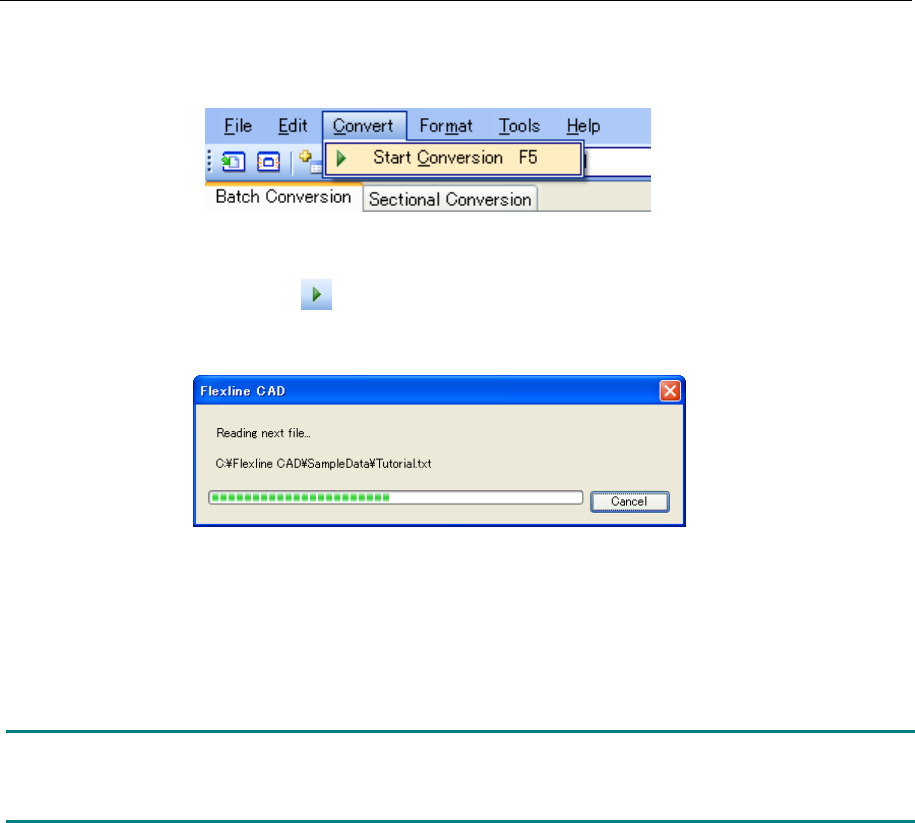
Select the line header of the line to be displayed. The selected line color is reversed.
Figure 6.2-7 Selecting a file
After specifying the line to be displayed, execute one of the following operations of (1) and (2).
(1) Select the "File" - "View Input File" menu.
Figure 6.2-8 “File”- “View Input File” menu
(2) Click "View Input File" ( ) of the tool bar.
The selected file is displayed by the application related to the file extension.
Select the line to be displayed with this header.
34
6.3 Converting CAD data
Execute either one of the following operations of (1) and (2).
(1) Select the "Convert" - "Start conversion"
Figure 6.3-1 "Convert" - "Start conversion" menu
(2) Click "Start conversion" ( ) of the tool bar.
Conversion is started and a dialog box to indicate the progress of conversion is displayed.
Figure 6.3-2 Progress status dialog box
The converted file is saved into the path specified in "Output file" of the file table. (The output
file saving destination and the output file name can also be changed. However, its explanation
is omitted.)
Note: If the decimal-place digits of the numeric value set in CAD data are different from the
corresponding unit of the output format, conversion is performed according to the unit of
numeric value of the corresponding model of the output format.