FLEXLINE-CAD_INM.pdf - 第126页
C-6 ♦ .N CD Data File . NCD Data Sample Example 1 (M K2 data file): N001/0G0M 902T0X - 18175Y - 515Z1V1W 1 N002/0G0M 902T0X10750Y0Z1V 1W 1 N003/0G1M 0T4X+Y+ Z+V+W + N004/0G0M 4T0X6990Y6645Z20V 1W 1 N005/0G0M 4T0X6990Y642…
C-5
♦
"Panasonic"
There are two types of Placement data files as follows:
.NCD data file
.POS data file
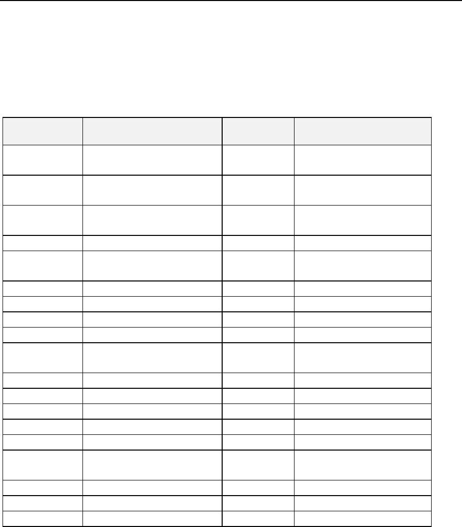
The following table describes the relationship among the Panasonic machine name, machine
number, file type and the input format names supported by Flexline CAD.
Table Pana-1 Panasonic Machines and Flexline CAD Input Formats
Machine
Name
Machine Number File Type
Input Format in Flexline
CAD
MPA 40 / 80 NM-2528
NM-2529
NCD MPA4080
MPA NM-2523
NM-2524
NCD
MPA
MK1C NM-2562C
NM-2565C
NCD
MK1C
MK2C
NM-2563C
NCD
MK2C
MK1 NM-2562
NM-2662B
NCD
MK1
MK2
NM-2563
NCD
MK2
MKH NM-2564 NCD MKH
MR NM-2560 NCD MR
MR 20 / 3
NM-2560
NCD
MR20
MQ1 NM-8256C
NM-8257C
NCD MQ1
MQ2
NM-8251C
NCD
MQ2
HD
NM-2621
NCD
HD
HD3
NM-2626C
NCD
HD3
MVI NCD MV1
MVIIA-B
NCD
MV2AB
MVII-C,F NM-2558
NM-2559
POS MV2C
MV2F
MPAIII
POS
MPA3
MSH1
POS
MSH1
MPA-V
POS
MPAV
The Panasonic data type uses two methods. XY coordinates can be entered with the absolute
method or the incremental method. Flexline CAD only supports ABS method.
Absolute method (ABS): Coordinate origin is always the basis for the placement position of
each component.
Incremental (INC): Placement position of each component is not determined from the
coordinates’ origin. Instead, it is determined to be the travel distance from the placement
position of the previous component. Therefore, X and Y coordinates represent the distance
from the center of one component’s placement position to the center of the next
component’s placement position.
C-6
♦
.NCD Data File
.NCD Data Sample
Example 1 (MK2 data file):
N001/0G0M902T0X-18175Y-515Z1V1W1
N002/0G0M902T0X10750Y0Z1V1W1
N003/0G1M0T4X+Y+Z+V+W+
N004/0G0M4T0X6990Y6645Z20V1W1
N005/0G0M4T0X6990Y6420Z20V1W1
N006/0G0M4T0X6990Y6185Z20V1W1
N007/0G0M4T0X6990Y5505Z20V1W1
……
N051*
Example 2 (MV data file):
N0001/0G0M902T000X+000000Y+000000Z+00000V+00000W+00000+00000D
N0002/1G1M000T004X0000000Y0000000Z000000V000000W000000+00000D
N0003/0G0M001T000X+003001Y-008374Z+00001V+00090W+00090+00000D
N0004/0G0M001T000X+009876Y-008124Z+00001V+00000W+00000+00000D
N0005/0G0M001T000X-001549Y-018449Z+00001V+00090W+00090+00000D
N0006/0G0M001T000X-004374Y-024624Z+00002V+00090W+00090+00000D
N0007/0G0M001T000X-004399Y-025824Z+00003V+00090W+00090+00000D
………..
N0489/0G0M001T000X+012951Y-011099Z+00111V+00000W+00000+00000D
*
PCB Data
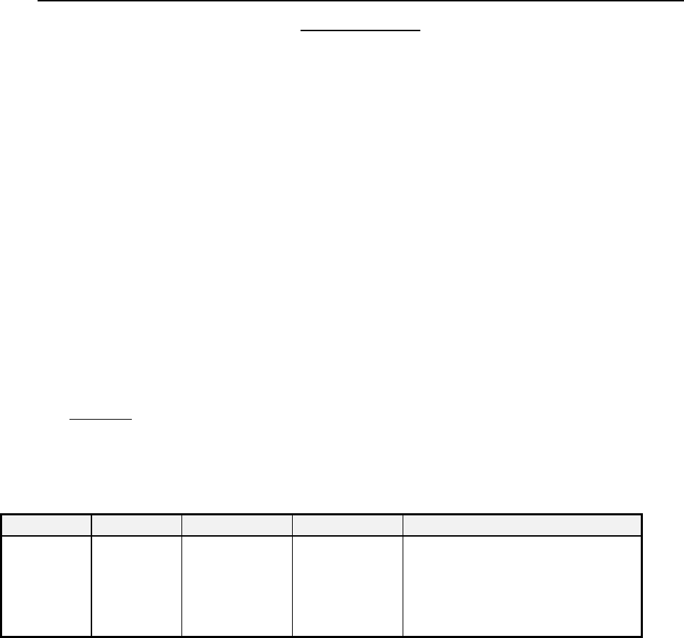
According to the placement data file, the field “PCB Board Type” is identified as shown in Table Pana-2
below:
Table Pana-2: Panasonic Data Format PCB Board Type
Data Item
Lines
Sections
Fields
Translation
PCB Board
Type
The first line
of the .NCD
data file
“SECTION_0” The field that is
tagged by the
keyword “M” in
the data line.
The string “901,” “902,” “911,” “912,”
“921,” “922,” “931,”or “932,” indicates
that the board is a “Non-Matrix Board."
Any other strings indicate that the
board is a “Single Board.”
If the result of the PCB Board Type is “Non-Matrix," the software will search the whole .NCD file and
pick up all the data lines with the M command tagged with string “901,” “902,” “911,” “912,” “921,” “922,”
“931,”or “932.” These lines will be regarded as the Non-Matrix data lines and the software will extract
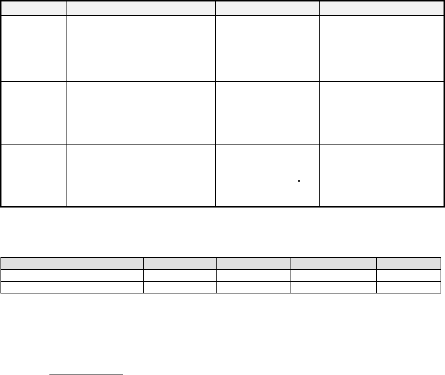
the circuit position X and Y and Angle in the way described in Table Pana-3 as shown below:
C-7
Table Pana-3: Panasonic .NCD Data Format NON-MATRIX section
Data Item
Lines
Field
Units
Scaling
Circuit
Position X
The several beginning lines with
the M command tagged with string
“901,” “902,” “911,” “912,” “921,”
“922,” “931,”or “932.”
The field that is tagged
with the keyword “X” in
the data line.
Millimeters 1/100
Circuit
Position Y
The several beginning lines with
the M command tagged with string
“901,” “902,” “911,” “912,” “921,”
“922,” “931,”or “932.”
The field that is tagged
with the keyword “Y” in
the data line.
Millimeters 1/100
Circuit
Position
Angle
The several beginning lines with
the M command tagged with string
“901,” “902,” “911,” “912,” “921,”
“922,” “931,”or “932.”
The middle number “x”
that is extracted from
string “9x1” or “9x2”.of
the keyword "M."
Degree **
** To understand the Circuit Position Angle, please see the table below:
Table Pana-4: Panasonic .NCD Data Format NON-MATRIX section Circuit Angle Code Number
M Command
901,902
911,912
921,922
931,932
Circuit Angle Code Number
0
1
2
3
Degree
0
90
180
270
Based on our understanding of the Panasonic data file, the first circuit’s position is with respect to
their machine’s origin. In HLC we do not need this data; therefore, we will set this position to
(0,0). The circuit layout offset X and Y must be manually entered into HLC.
Placement Data
The PLACEMENT data lines for the Panasonic is determined by the “G” and “M” commands of
the data line in the NCD data file.