FLEXLINE-CAD_INM.pdf - 第98页
A-1 A ppendix A Practice : Creating an I nput File by Using the A tt ached File "T utorial.txt" T ry to create an input format for conv erting the file "T utorial.txt " that is att ached to Flexl ine …

92
Layer Layer 1
Layer 2
Layer 3
Layer 4
Layer 5
Layer 6
Layer 7
Layer 8
Layer 9
Layer 10
Placement machine Auto selection
Machine 1
Machine 2
Machine 3
Machine 4
Machine 5
Machine 6
Machine 7
Machine 8
Machine 9
Machine 10
Placement head
Default head
Left head
Middle head
Right head
Dispensing skip Skip
No skip
Dispensing test run Dispensing by test run
No dispensing by test run
Dispensing machine
Auto selection
Machine 1
Machine 2
Machine 3
Machine 4
Machine 5
Machine 6
Machine 7
Machine 8
Machine 9
Machine 10
Dispensing head
Default head
Left head
Middle head
Right head
Component
Valid
Valid
Invalid
Invalid
A-1
Appendix A Practice: Creating an Input File by Using the
Attached File "Tutorial.txt"
Try to create an input format for converting the file "Tutorial.txt" that is attached to Flexline CAD
as the standard.
1. Looking into the Contents of "Tutorial.txt"
1.1 Looking at the contents of Tutorial.txt by using Explorer (For Windows)
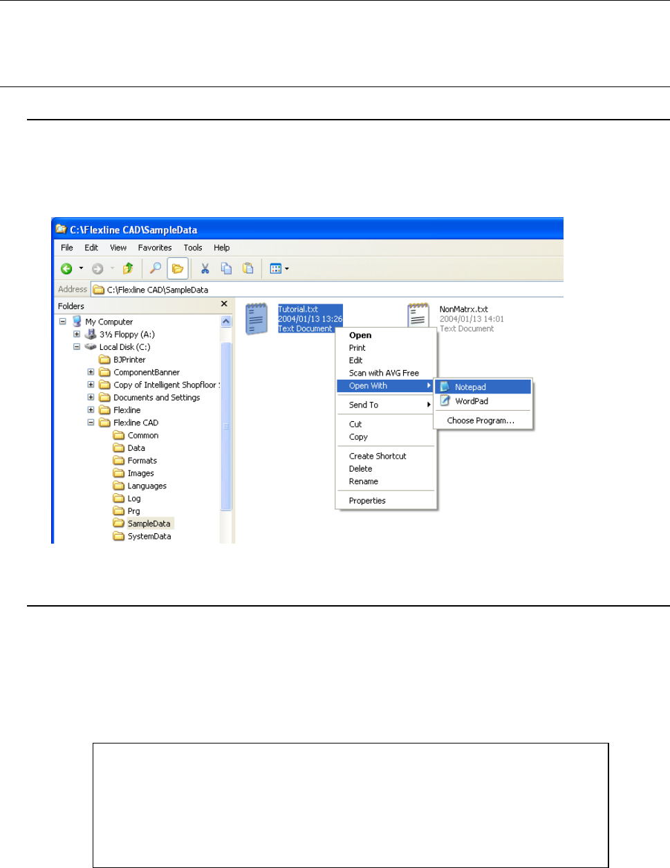
1) Start Explorer and select "{Flexline CAD install folder}\SampleData".
2) Select Turorial.txt and double-click it with the left mouse button or click it with the right
mouse button. Then, select "Notepad" command from the displayed menu.
Figure A-1 Tutorial.txt selection screen
1.2 Contents of Tutorial.txt
Tutorial.txt consists of PWB data, placement data, and component data.
• PWB data: This information contains PWB ID, outer dimension, PWB layout offset, and
BOC mark coordinates (2 points).
• Placement data: The section layout uses the tag (PLC) and the field layout uses the fixed
length.
• Component data: The placement ID and the component name are separated by ",".
Figure A-2 PWB dada of Tutorial.txt
!Flexline CAD Tutorial
Flexline CAD Tutorial PWB
150000 100000
150000 000000
10000 10000 145000 95000

A-2
Figure A-3 Placement data of Tutorial.txt
Figure A-4 Component data of Tutorial.txt
Component Name and Comment
Q1,"2N2886"
Q2,"BC147"
U1,"74HCT241"
C1,"CAP 22PF, 5%, 50V"
C2,"CAP 0.1MF, 10%, 50V"
C3,"220 MF"
C4,"ECU-V1H103KBW .01 uF"
C5,"CAP 2.2MF, 10%, 50V"
D1,"1N4148 signal diode"
D2,"1N4001X200V "
U2,"LM781CTB TO-220X VAL"
U3,"LTC1421CG"
U4,"MOC3020N"
Q3,"FETP_220 IRF9523"
XTAL1,"XFMR2WCT"
R1,"RES400 1.2K"
R2,"RES 2K 1% 1/10W"
R3,"RES 332 OHM 1% 1/10W"
R4,"RES400 1.2K"
R5,"RES 2K 1% 1/10W"
R6,"RES 332 OHM 1% 1/10W"
R7,"RES400 1.2K"
R8,"RES 2K 1% 1/10W"
R9,"RES 332 OHM 1% 1/10W"
Date 3/8/98
!TAG ID +XXXXXX+YYYYYY+AAA+S CCCCCCCCCCCCCCCC
PLC_0001+005000+000640+000 T Q1
PLC_0002+004350+001230+090 T Q2
PLC_0003+032560+023440+000 T U1
PLC_0004+007670+086540+270 B C1
PLC_0005+003450+075630+090 T C2
PLC_0006+035030+034350+000 T C3
PLC_0007+007600+054750+180 B U2
PLC_0008+023550+034600+090 T C4
PLC_0009+034670+003340+000 T C5
PLC_0010+098970+003450+090 B U3
PLC_0011+066560+045460+270 T U4
PLC_0012+045650+067430+090 B D1
PLC_0013+003660+023450+000 T D2
PLC_0014+004523+046560+090 B Q3
PLC_0015+026640+034660+000 T XTAL1
PLC_0016+012340+032370+090 B R1
PLC_0017+004560+037370+070 T R2
PLC_0018+001230+022440+045 T R3
PLC_0019+012340+059860+090 T R4
PLC_0020+004560+066660+070 B R5
PLC_0021+001230+034550+045 T R6
PLC_0022+012340+023450+090 B R7
PLC_0023+004560+023560+070 T R8
PLC_0024+001230+087450+045 T R9