FLEXLINE-CAD_INM.pdf - 第66页
61 7.6.2 BOM (Bill of Material: Component T able) On the "Field translation" scr een for component data, t he "BOM settings" scr een is displayed. Check off "Enable BOM link" on the "BO…
60
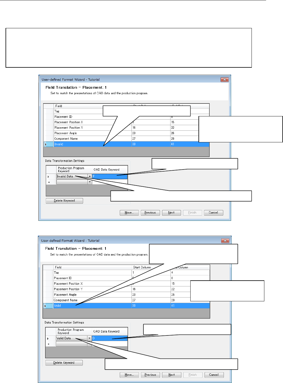
7.6.1 Definition of valid/invalid data
To convert only line 3 to line 5 ignoring line 1 and line 2 when the following data exists, set the
lines containing "F" to Invalid (or lines containing "D" to Valid).
(1 1 "F" 1 -30908 307 0 0 0 0 0 "R1" "" "" "" "" 0 0 0 2 0 0 0 0 0 0 0 "" )
( 2 1 "F" 1 -3231 27734 0 0 0 0 0 "R1" "" "" "" "" 0 0 0 1 0 0 0 0 0 0 0 "" )
( 3 1 "D" 1 -30274 5385 5400 1 2 0 0 "F222" "" "" "" "" 0 0 0 0 0 0 0 0 0 0 0 "" )
( 4 1 "D" 2 -30783 3863 5400 1 2 0 0 "F05" "" "" "" "" 0 0 0 0 0 0 0 0 0 0 0 "" )
( 5 1 "D" 1 -29384 3352 5400 1 2 0 0 "F345" "" "" "" "" 0 0 0 0 0 0 0 0 0 0 0 "" )
Figure 7.6.1-1 Field translation (Invalid Data setting)
Figure 7.6.1-2 Field Translation (Valid Data setting)
1. Select the line to set field.
3. Enter "F" in CAD Data Keyword.
2. Select "Invalid Data" in Production Program Keyword.
* When "Invalid Data" is defined,
not only "Invalid Data" fields
but also the whole line are not
converted.
1. Select the line to set field.
translation.
* In each section, up to 10
"Valid Data" and "Invalid
Data" can be defined.
3. Enter "D" in CAD Data Keyword.
2. Select "Valid data" in Production Program Keyword.
61
7.6.2 BOM (Bill of Material: Component Table)
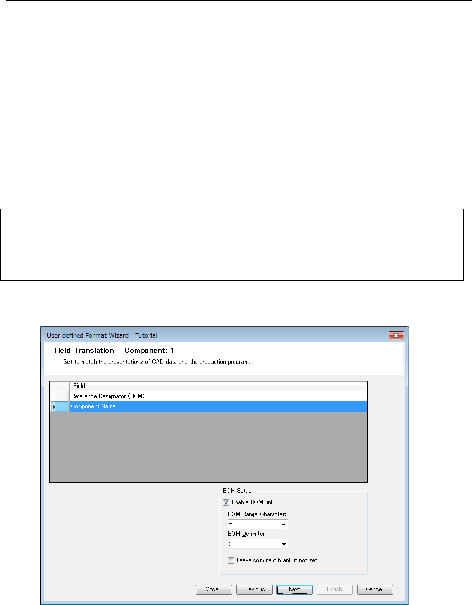
On the "Field translation" screen for component data, the "BOM settings" screen is displayed.
Check off "Enable BOM link" on the "BOM settings" screen. Then, when the same placement ID
is used for component data and placement data, the component name is copied to the
placement data.
In the case of "tutorial.txt", the placement data contains an placement ID but not any component
ID. Since the component data contains a placement ID, this component name is incorporated
into the placement data at transformation.
In "tutorial.txt", one placement ID is provided for one component name. In some cases,
however, multiple placement IDs may be provided for one component name. At this time, use
"BOM range character" and "BOM delimiter" are used as a specifying method.
When CAD data is defined as shown below, enter "-" into "BOM range character" and ";" into
"BOM delimiter."
Q1,"CAP 22PF, 5%, 50V(SMD1206)"
Q2,"74HCT241 (SMD SOL)"
U1-U9,"BC147" ←Component name of "BC147" for placement IDs of U1 to U9
C1;C4;C7-C11,"2N2886" ← Component name of "2N2886" for placement IDs of C1, C4, C7
to C11
"-" (hyphen), ":" (colon), "." (period) are available for BOM range characters.
"," (comma), ";" (semi-colon), and "/" (slash) are available for BOM delimiters.
Figure 7.6-2-1 Field Translation
62
NOTES
- If you use the BOM link without specifying the "BOM Range Character," the system
recognizes all the applicable characters as the "BOM Range Character." When you do not
use the "BOM Range Character," specify the "NONE" from the choices. The same holds for
the "BOM Delimiter."
- Only when a component comment is defined by using the BOM link in the user-defined
wizard, it is possible to set the option "Leave comment blank if not set" from the field
translation screen of the component section. If this option is not checked off, the
component reference designator is written into the output file as a comment.
- When you perform data transformation by using the user-defined format using the BOM
link, the maximum number of characters that can be entered in the "Reference designator"
field of the component data is 2048 as the default.
- When more than 2048 characters are used in the "Reference designator" field of the CAD
data file, the data (such as the same component is placed repeatedly on the same PWB)
exceeding 2048 characters is truncated. Accordingly, if the "Reference designator"
exceeding 2048 characters is used, divide the "Reference designator" field in the CAD data
file into two or three fields.
- If BOM data and placement data cannot be linked at transformation, the message "Linking
placement data and component data failed. Continue processing?" is displayed. At "Yes",
the processing is continued. At "No", the processing is stopped.
BOM link
At transformation, the "Placement ID" or "Link ID" of the placement section is linked with the
"Reference designator (BOM) of the component section. Using the "Placement ID" or "Link
ID" of the placement section depends on the following conditions:
1. When the "Link ID" is not defined in the placement section, the "Placement ID" of the
placement section is linked with the "Reference designator (BOM)" of the component
section to perform BOM link.
2. When the "Link ID" is defined in the placement section, the "Link ID" is linked with the
"Reference designator" of the component section to perform BOM link regardless of
whether the "Placement ID" is defined.
After execution of BOM link, a component name which exists in the placement section is
overwritten on the component name linked from the component section. If no component
name is found in the placement section, a component name field is added.
7.7 User-defined wizard finish screen
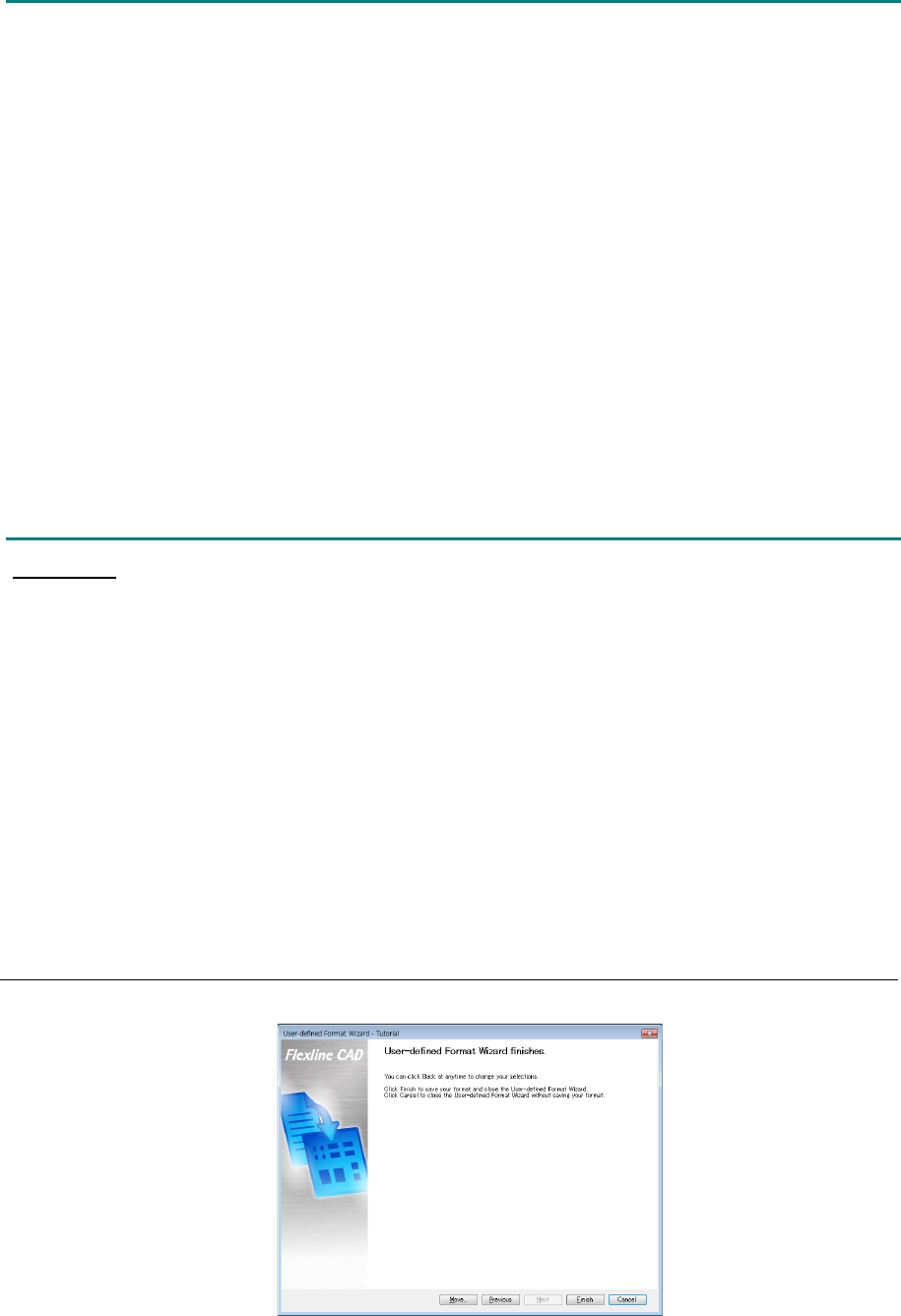
After all the settings are completed, the following screen is displayed.
Figure 7.7-1 Finish of user-defined wizard