FLEXLINE-CAD_INM.pdf - 第47页
42 7.3 Coordina te trans format ion In CAD data, t he position and direction of the component to be placed on the PW B are described. For this purpose, various coordinate sy stems are adopted. I n the case of some CAD da…
41
When defining the multi-circuit non-matrix, the circuit layout field (X, Y, and angle of multi-
circuit non-matrix circuit position) and other fields cannot be defined in the same PWB
section.
For details, refer to the last part of Appendix A.
When PWB data exists in multiple positions, set the number of PWB sections to 2 so that the
PWB data can be defined by dividing it into two parts. In the following example, the PWB ID is
defined in the first place and the PWB outer dimensions, PWB layout offset, and BOC mark
position are defined in the second place.
Flexline CAD Tutorial PWB ⇐ PWB ID
TR1, 85, 65, 0, sot23 ⇐ Placement data
TR2, 100, 50, 90, sot23 ⇐ Placement data
165, 125, 165, 0, 5, 10, 160, 120 ⇐ PWB outer dimensions, PWB layout
offset, BOC mark position
Note: The data that cannot be defined once cannot be converted by Flexline CAD.
7.2.3 PWB unit and placement unit
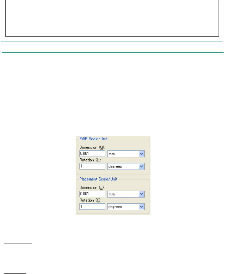
When the number of sections of "PWB" or "placement" is set to 1 or more in "Section", "PWB
scale/unit" or "Placement scale/unit" can be used. The scale and unit related to dimension and
rotation can be set.
The dimension unit can be selected out of "mm", "1/100 mm", "cm", "inches", and "mils". The
rotation unit can be selected out of "degrees" and "radians."
The unit is selected by default, which was set in “Change” – “Unit of default” in the environment
setup.
Figure 7.2.3-1 Unit
The unit converting method is as follows:
Dimension
1 inch = 2.540 (x) 1/100 mm = 25.4 mm = 2.54 cm = 1000 mils
1 mils = 2.54 (x) 1/100 mm = 1/1000 inch = 0.0254 mm = 0.00254 cm
Rotation
2 π rad (radian) = 360º (degree) (π = 3.141592654 ...)
1º (degree) = (π ÷ 180) rad (radian)
42
7.3 Coordinate transformation
In CAD data, the position and direction of the component to be placed on the PWB are
described. For this purpose, various coordinate systems are adopted. In the case of some CAD
data types, the unit of dimension is different. To process a new format, Flexline CAD converts
the numeric data of the data file into an amount measured on the JUKI standard direction and
standard system.
* In coordinate transformation of the "Global Setup" screen, select the transformation type.
7.3.1 Standard Transformation Settings screen
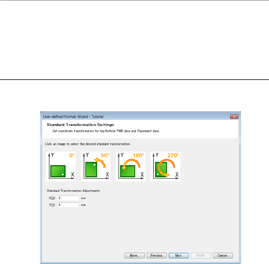
In coordinate transformation of the "Global Setup" screen, specify "Standard transformation"
and click the [Next] button. Then, the following screen is displayed. Click one image of "0º",
"90º", "180º", and "270º" and set Coordinate transformation.
Figure 7.3.1-1 Standard Transformation Settings
* The rotation angle specified here is used for conversion of PWB data and placement data
of both top side and bottom side.
43
7.3.2 Custom transformation settings (PWB) screen
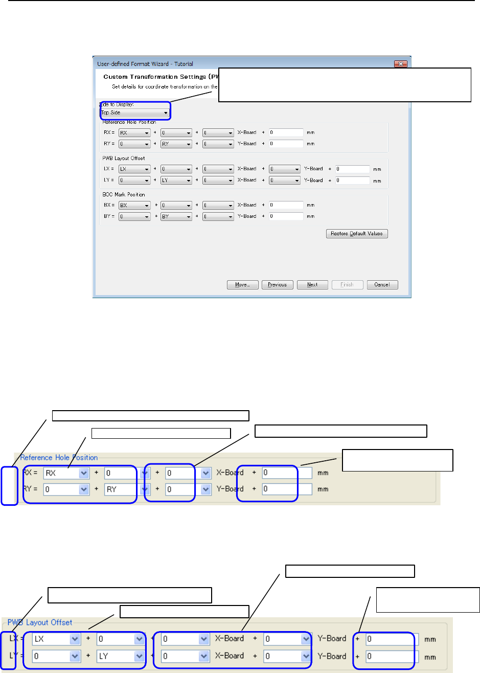
In coordinate transformation of the "Global Setup" screen, specify "Custom transformation"
and click the [Next] button. Then, the following screen is displayed.
Figure 7.3.2-1 Custom Transformation Settings (PWB)
* Click the "Restore Default Values" button to set the default values for all the values displayed
on the screen.
Reference hole position
An expression to convert the reference hole position data into the standard transformation
system is defined.
Figure 7.3.2-2 Reference hole position
PWB layout offset
An expression to convert the PWB layout offset data into the standard coordinate system is
defined.
Figure 7.3.2-3 PWB Layout Offset
From the pull-down menu, select this item and set each
of the top side and bottom side.
Reference hole position after transformation
Reference hole position of CAD data
PWB dimension increment/decrement value
Other increment/decrement
value
PWB layout offset of CAD data
PWB increment/decrement value
PWB layout offset after transformation
Other
increment/decrement