FLEXLINE-CAD_INM.pdf - 第70页
65 Figure 7.8.3 -2 “Move” di alog box displ ayed if any of the screens is not set up compl etely W hen you increase the number of PW Bs on the “Global Setup” screen, it is also supposed that there is a scr een whose sett…
64
10 “Field Definition” screen ×
11 “Field Translation” screen ×
- Component -
All of section definition, field definition and field
translation of “Component” have been completed.
12
“Section Definition” screen
○
13
“Field Definition” screen
×
14
“Field Translation” screen
×
15
“User-defined Format Wizard
finishes” screen
×
○
: You can move to this screen from the “Move” dialog box.
×: You cannot move to this screen from the “Move” dialog box.
7.8.3 Operating the “Move” dialog box
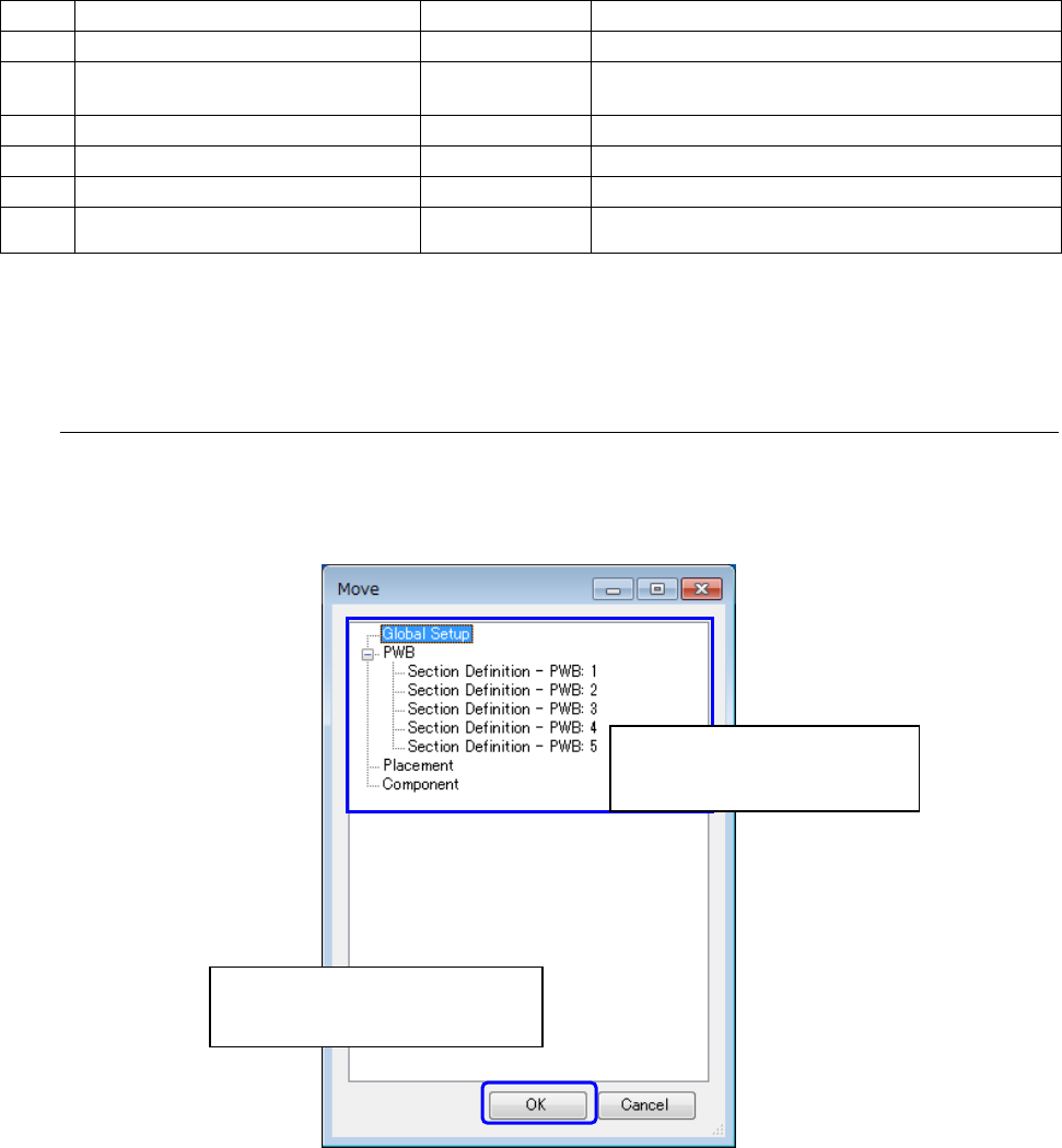
When you select the screen to which you want to move on the “Move” dialog box and click the
“OK” button, you can move to the selected screen. If you do not move to the selected screen,
click the “Cancel” button.
Figure 7.8.3-1
Operating the “Move” dialog box
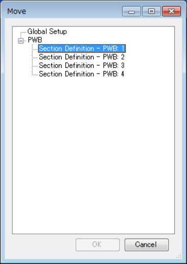
If any of the screens is not set up completely, you cannot move to the corresponding next
screen of the User-defined Format Wizard. For example, if you display the “Move” dialog box
after setting the PWBs “1 to 5” on the “Global Setup” screen and making settings of the PWBs
“1 to 4” completely, you cannot move to any of the following screens: “PWB 5,” “Placement”
and “Component.” In this case, the “Move” dialog box is displayed as shown in Figure 7-8-3-2
““Move” dialog box displayed if any of the screens is not set up completely.”
①
Select the screen to which you
want to move.
②
Select the screen to which you
want to move. Click the “OK”
65
Figure 7.8.3-2
“Move” dialog box displayed
if any of the screens is not set up completely
When you increase the number of PWBs on the “Global Setup” screen, it is also supposed
that there is a screen whose setting is not made completely. For example, if you perform the
following operations, the PWB “5” is not set up completely in Step 5, and you cannot move to
any of the screens: “PWB 5,” “Placement” and “Component.” In this case, the screen
described above appears also.
1 Specify “4” in the “PWB” field, “1” in the “Placement” field, and “1” in the “Component” field
on the “Global Setup” screen.
2 Click the “Next” button on the “Field Translation – Component” screen to display the “User-
defined Format Wizard finishes” screen.
3 Display the “Move” dialog box on the “User-defined Format Wizard finishes” screen, and
then move to the “Global Setup” screen.
4 Change the setting of the “PWB” field to “5” on the “Global Setup” screen.
5 Display the “Move” dialog box on the “Global Setup” screen.
66
Chapter 8 Data modification dialog box *1
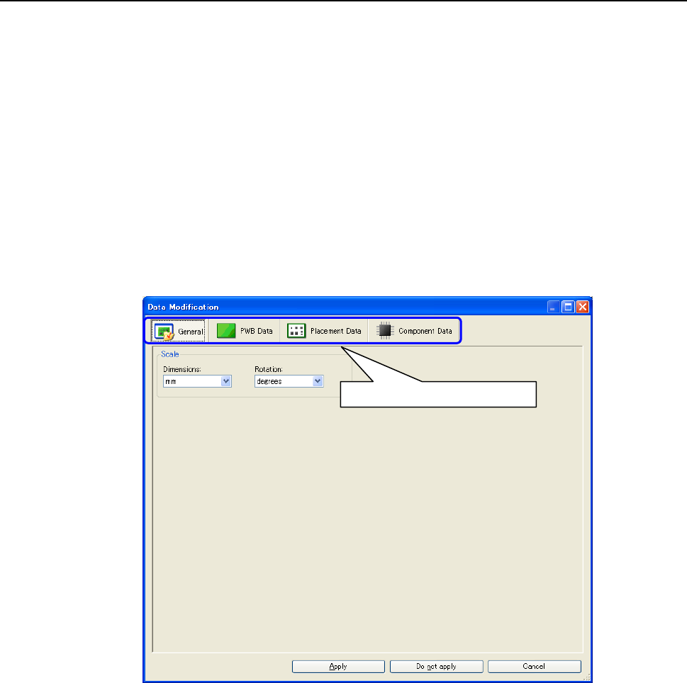
Before data is output, it can be edited.
Regarding three sections (PWB data, placement data, and component data), data items can be
modified. PWB data items that are not provided in the input file can also be added. For
placement data and component data, however, only modification can be performed but addition
cannot be performed.
* Data editing and addition can also be performed by machine, The production support
system after CAD conversion. Accordingly, the data modification dialog box is not always
required.
* The display/on-splay of the data modification dialog box is set in Environment settings. For
how to display the data modification dialog box, refer to "9.1.3 Conversion setting screen."
After conversion is started, the data modification dialog box is displayed during conversion
when the display of the data modification dialog box is set.
Figure 8-1 Data modification dialog box
*1 The screen displayed with the Version 5.10 or earlier is different from that with the Version
6.00 or later.
Click it to switch the display data.