FLEXLINE-CAD_INM.pdf - 第115页
A- 18 2. Read the file. In the "Section Layout", select the "Line Range" and enter 10 in the " S tart Line" and 13 in "End Line." Figure A - 29 Section Definition screen ( PWB 1) …
A-17
* Define non-matrix boards
To define a non-matrix board in the User-defined Format Wizard, the circuit position data
needs to be stored as a table or array data in the input file. Each circuit position must be on a
separate line.
[Example]
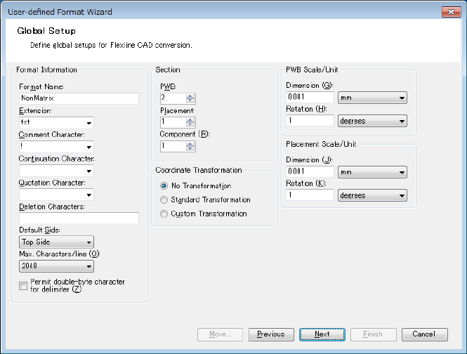
Define a non-matrix board as follows:
1. Since you cannot define the non-matrix PWB position data and other PWB related data in
the same PWB section, you need to specify 2 PWB sections at the beginning.
Figure A-28 Global Setup screen
Click the "Next" button.
A-18
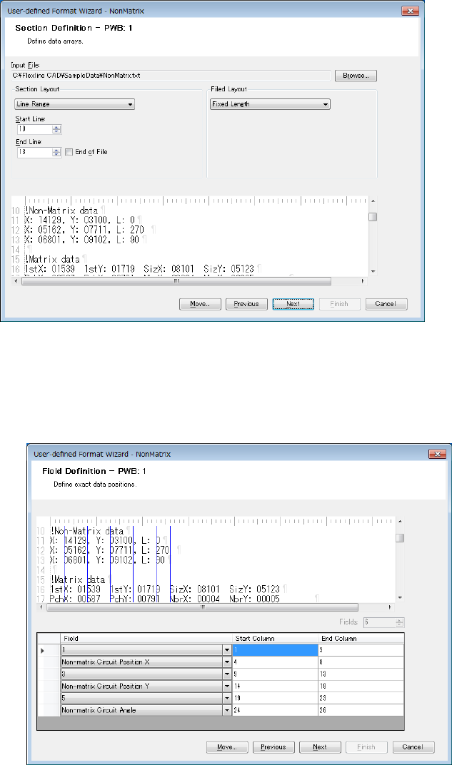
2. Read the file. In the "Section Layout", select the "Line Range" and enter 10 in the "Start
Line" and 13 in "End Line."
Figure A-29 Section Definition screen (PWB 1)
Click the "Next" button.
3. Set the "Non-matrix Circuit Position X", "Non-matrix Circuit Position Y", and Non-matrix
Circuit Angle."
Figure A-30 Field Definition screen (PWB 1)
When defining the circuit layout data, it is not possible to define other fields in the same
PWB section.
Click the "Next" button.
A-19
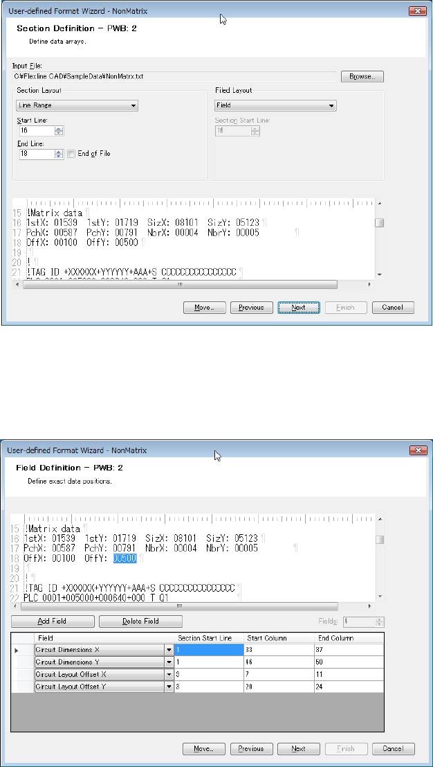
4. The circuit layout offset and circuit outer dimensions of matrix PWB are defined on the
second PWB section definition screen. In the "Section Layout", select "Line Range" and
enter 16 in the "Start Line" and 18 in "End Line." In the "Field Layout", select "Field."
Figure A-31 Section Definition screen (PWB 2)
Click the "Next" button.
5. Set the Circuit Layout Offset X, Circuit Layout Offset Y, and Circuit Dimensions X/Y. Set the
Circuit Layout Offset X, Circuit Layout Offset Y, and Circuit Dimensions X/Y.
Figure A-32 Field definition screen (PWB 2)