FLEXLINE-CAD_INM.pdf - 第9页
4 1.2 Intr oduction Welcome to Flexline CAD This is a data conver sion system for Microsoft W indows. The system can conv ert these files into production programs of JUKI mounters, or t he production support sy stem . Fl…

3
Before using this manual, the user must be well versed in operating our mounter (KE series),
and also have a good understanding of basic operations of Windows. This manual is
described on the assumption that the user should have understood how to operate Windows
and how to use menus or dialog box boxes. For operating these, refer to the Windows
manuals.
The user may use this manual together with the on-line help of Flexline CAD.
The displayed screens and some functions of Flexline CAD Version 5.10 or earlier are
different from those of Version 6.00 or later. See the following notes:
*1 The screens displayed with Flexline CAD Version 5.10 or earlier are different from those of
the Version 6.00 or later.
*2 Enabled with Flexline CAD Version 6.00 or later only. (Some functions may be enabled
with the latest version only.)
*3 Enabled with Flexline CAD Version 5.10 or earlier.

4
1.2 Introduction
Welcome to Flexline CAD
This is a data conversion system for Microsoft Windows. The system can convert these files into
production programs of JUKI mounters, or the production support system.
Flexline CAD as graphical software
This system makes the most of the graphical operating environment provided by Windows.
Accordingly, everyone can easily operate this system.
High compatibility
The compatibility with wade-range of CAD packages is provided by CAD data file format
describing function. The system has flexibility to meet various customers' requirements easily
and quickly.
Main functions of Flexline CAD
• Conversion of the data of various CAD systems including FLEX PROGRAM (former CAD
conversion software) and the production data of various companies. (ASCII format →
Production programs of various JUKI mounters, the production support system)
• Conversion into the ASCII format files (STF format) of JUKI production programs
1.3 Outline of Flexline CAD product
This CAD converts the data (PWB data, placement data, and component data of ASCII format
files) created different CAD systems so that these data can be used for various JUKI mounters
through a simple procedure.
For data conversion, an input format defining the CAD data file format is required. For the input
/ output format, see "10-1 Standard format". In case such a defined input format is not
available, the "user-defined wizard" (refer to "7. User-Defined Wizard") is used for creation.
5
Chapter 2 Outline of Operations
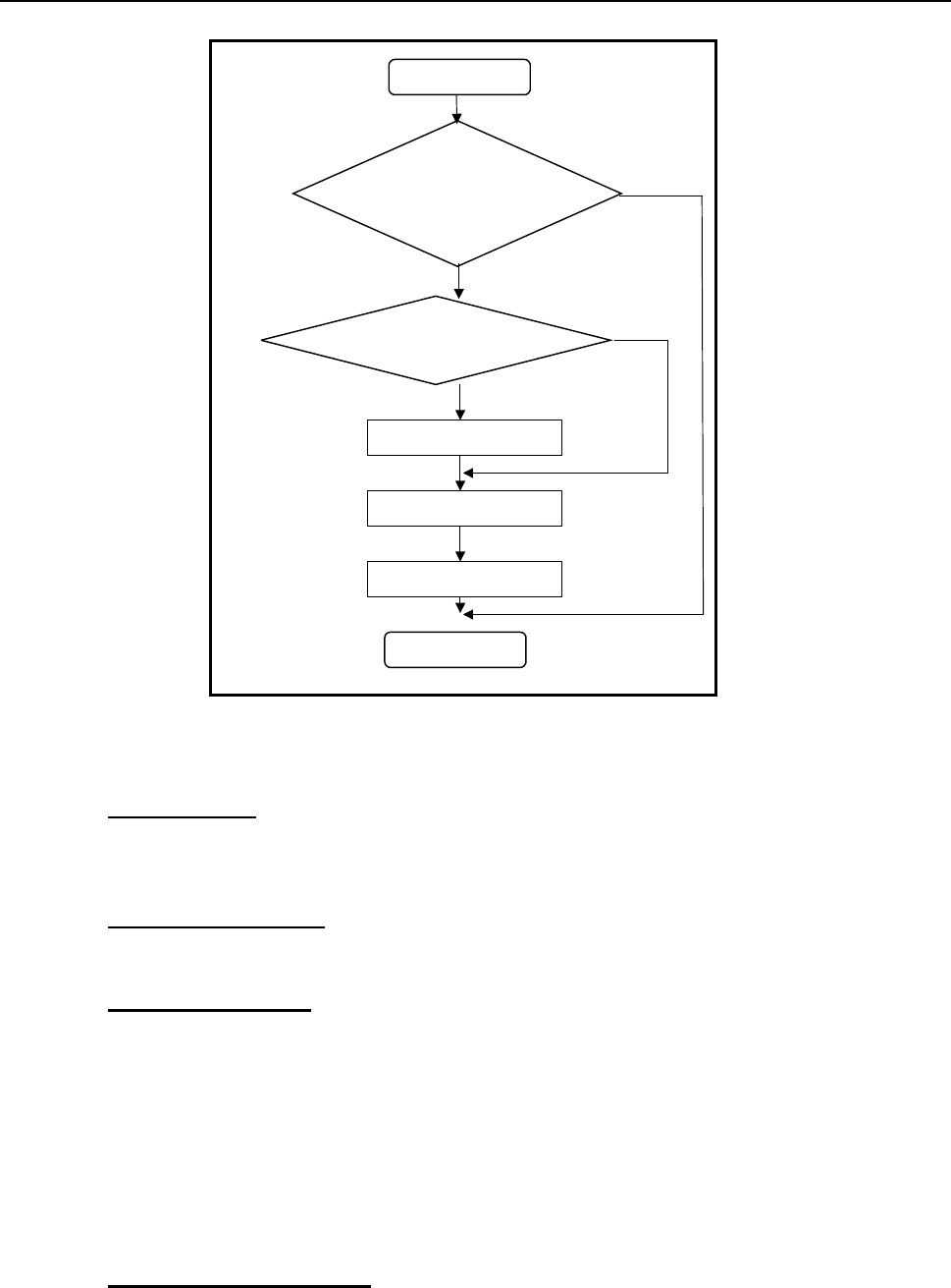
An outline of data conversion is shown below:
Conversion
Are the contents of CAD
data configured so as to
create an input format?
Is the input format available?
Create an input format
File output
No
Yes
No
Yes
CAD data
End
Figure 2-1 General data conversion flowchart of Flexline CAD
◇The items required to use Flexline CAD are as follows:
1. "Input format"
This means an input format that indicates the data sequence of the CAD data to be
converted. Define the input format before CAD conversion and select a format for a file
(CAD data, etc.) to be converted at conversion. Thus, the CAD data file is converted.
2. "Environment setup"
Set the defaults of this CAD, set the output file format and conversion, and set display
items.
3. "Conversion mode"
Two types of data conversion mode, namely, "Sectional conversion mode" and "Batch
conversion mode" are prepared.
"Sectional conversion mode": This mode is used to convert single or multiple CAD data
file information into a production program of one mounter in combined form. This mode is
selected when PWB data, placement data, and component data are contained in different
files. The number of output files is always one.
"Batch conversion mode": This mode permits converting single or multiple CAD data files
simultaneously. For one CAD data, one production program is created. This mode is
suitable for simultaneous conversion of multiple files.
4. "Data change dialog box"
When specific items of data must be corrected before conversion, data correction can be
attained by using the data change dialog box.