FLEXLINE-CAD_INM.pdf - 第59页
54 7.5.2 Delimited This is a defining m ethod for the case w here the each item of the field is separated by delimi ter . Figur e 7.5.2 - 1 Fie ld definitio n (delimite r) 7.5.3 Field This is a defining m ethod when t he…
53
7.5 Field definition screen
The position of each data is accurately defined. The field position specifying method varies
depending on the field layout ("Fixed length," "Delimited," and "Field").
For the table of field names corresponding to the PWB section, placement section, and
component section, refer to "10.3 Field."
7.5.1 Fixed length
This is a defining method for the case where the length of each item of the field is fixed. The
field is defined by distinguishing each item by column (vertical column).
◊ There are some unnecessary field data and name assignment is not necessary for these
data. In this case, leave the field as a blank.
◊ To delete the set field, click the vertical line corresponding to the field to be deleted. The
vertical line and field line are deleted.
The set vertical line has no effect on other sections.
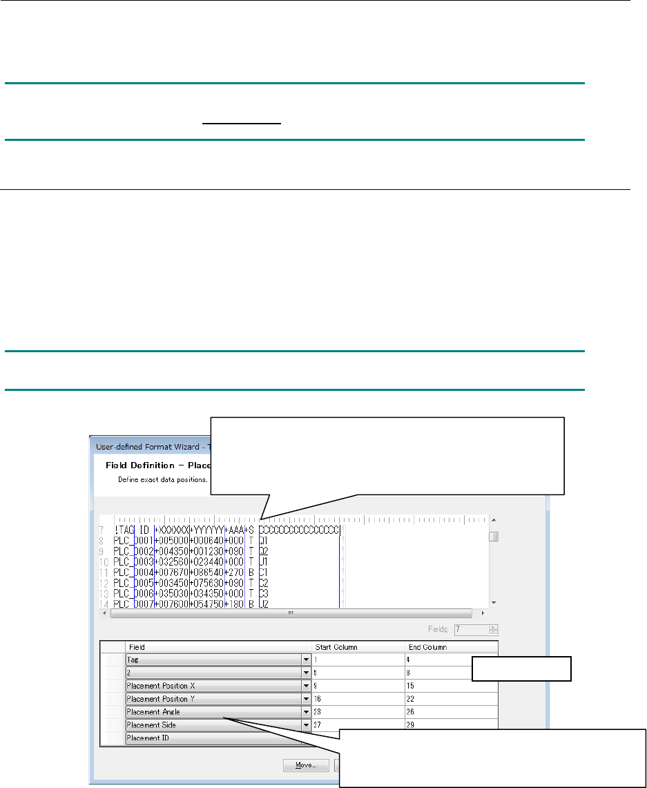
Figure 7.5.1-1 Field Definition (Fixed Length)
1. Click on the column to be separated to set the vertical line.
To delete the vertical line, click again on the vertical line.
*
The vertical line cannot be set on the blank area beyond
the rightmost column that has a character.
Data field area
2. After performing the setting of 1, the field line is
added automatically. Select the target field name
to be defined.
54
7.5.2 Delimited
This is a defining method for the case where the each item of the field is separated by delimiter.
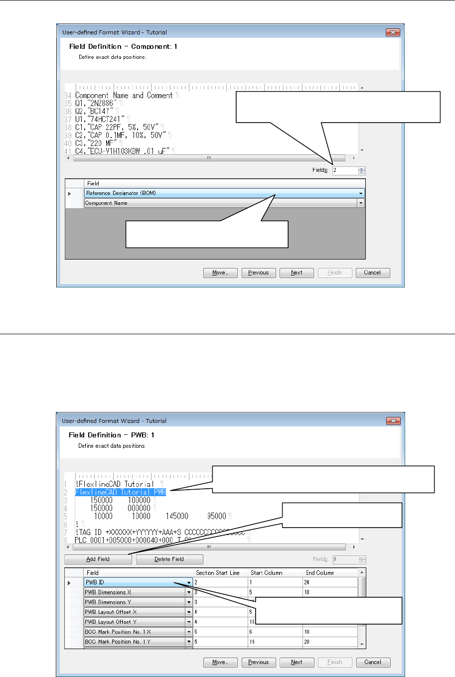
Figure 7.5.2-1 Field definition (delimiter)
7.5.3 Field
This is a defining method when the data has no regularity. Each item of data can be defined
optionally.
◊ On the section start line, the number of lines counted from the section start line set at the
field layout is displayed.
Figure 7.5.3-1 Field definition (field)
1. Enter the number of fields to be defined in
Fields and press the "Enter" key.
2. Select the target field name to be
defined.
1. Select the character string to be defined as the
field by mouse.
2. Click the "Add field"
button.
3. Select the target field name to
be defined.

55
7.5.4 Definition of IC mark ID at the placement section
The formats applicable to the IC mark ID are as follows: Even if data conversion is performed
with the other formats as an output format, no IC mark ID is output.
• HLC Ver 5.4 to 12.0
• IS 2.00
• IS,IS Lite
• 2010 Ver 2.00
• 2020 Ver 2.00
• 2030 Ver 2.00
• 2040 Ver 2.00
• 2050 Ver 1.XX
• 2050R Ver 1.XX
• 2055R Ver 1.XX
• 2060 Ver 1.XX
• 2060R Ver 1.XX
• 2070 Ver 1.00/1.XX/2.1X
• 2080 Ver 1.00/1.XX/2.1X
• 2080R Ver 2.1X
• 3020 Ver 1.00
• 3020R Ver 1.00
• 3010 Ver 1.00
• 3020V Ver 1.00
• 3020VR Ver 1.00
• 3010A Ver 1.00
• 3020VA Ver 1.00
• 3020VRA Ver 1.00
• FX-1 Ver 1.XX
• FX-1R Ver 1.XX
• FX-2 Ver 1.00/1.XX
• FX-3 Ver 1.00/1.XX/3.50
• FX-3R Ver 4.XX
• FX-3RA Ver 1.00
• CX-1 Ver 1.00/1.XX
• RX-6 Ver1.00
• RX-6R Ver4.00
• RS-1 Ver1.00
• LC-01
To convert the IC mark coordinate data with the above formats as output formats, be sure to
define the three fields of IC mark ID, IC mark type, and IC mark link by placement section.
When these data are not found in the input file, the contents of definition are blank. However, be
sure to define the field. The IC mark ID is automatically created for the output file.
NOTE:
Select the "IS, IS Lite" when you want to output in JaNets format.