FLEXLINE-CAD_INM.pdf - 第51页
46 <Exercise 1> * T ry to make a c alculation on the supposition of X coordinate = 50, Y c oordinate = 35, PW B dimens ion X = 300, and PW B dim ension Y = 200. In the case of X = [X] + [0] + [0]X - Board + [0], th…
45
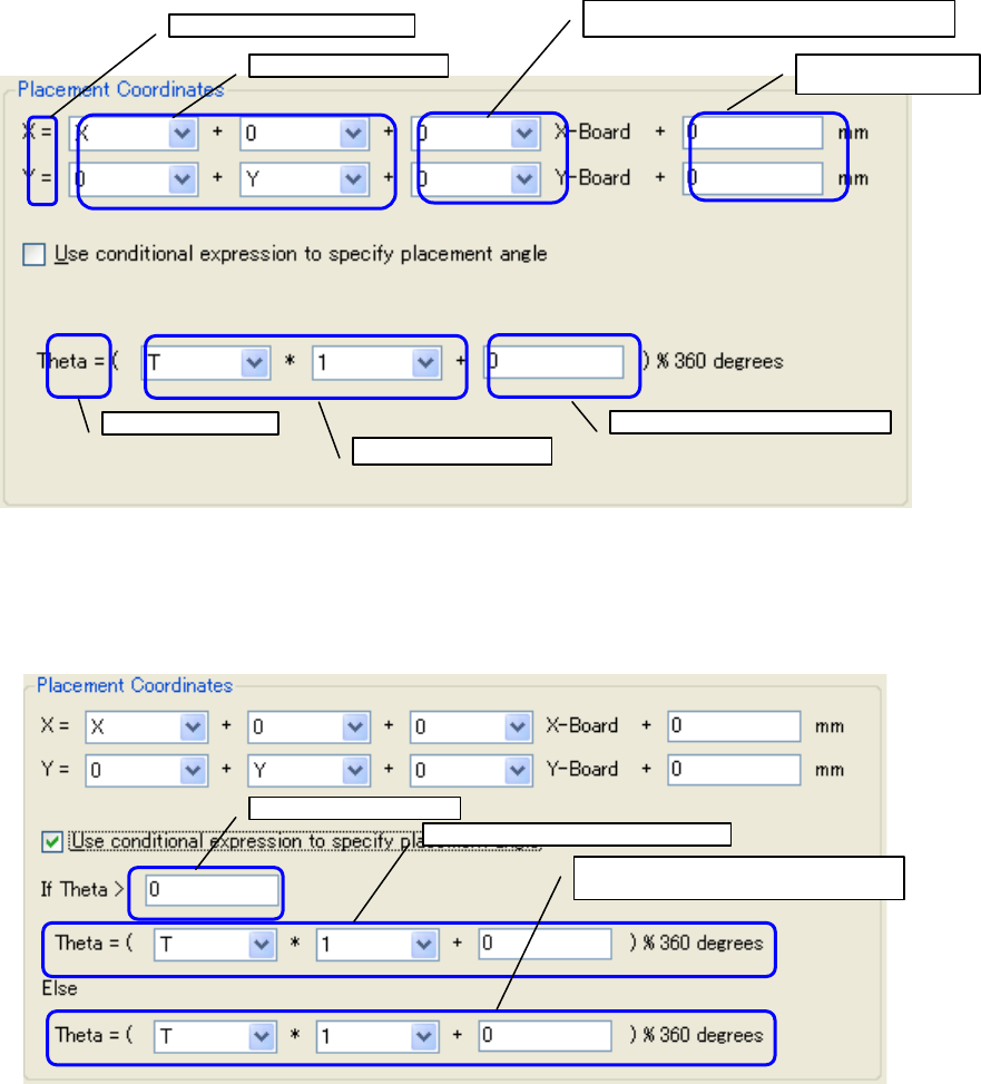
An expression to convert the placement data into the standard coordinate system is defined.
Figure 7.3.3-2 Placement Coordinates
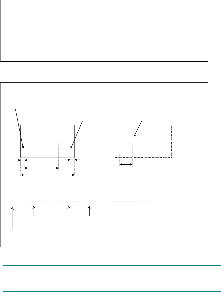
As one method of specifying the placement angle, a conditional expression can be set.
Check off "Use conditional expression to specify placement angle" to display the input screen
using the conditional expression.
Figure 7.3.3-3 Placement Coordinates (when using a conditional expression)
X and Y after transformation
X and Y of CAD data
PWB dimension increment/decrement value
Other
increment/decrement
θ after transformation
θ of CAD data
Other increment/decrement value
CAD data condition
Expression when the condition holds
Expression when the condition does not
hold
46
<Exercise 1>
* Try to make a calculation on the supposition of X coordinate = 50, Y coordinate = 35, PWB
dimension X = 300, and PWB dimension Y = 200.
In the case of X = [X] + [0] + [0]X - Board + [0], the X value after transformation is 50.
In the case of X = [X] + [0] + [1]X - Board + [0], the X value after transformation is 350.
In the case of X = [0] + [Y] + [0]X - Board + [0], the X value after transformation is 35.
In the case of X = [X] + [0] + [-1]X - Board + [0], the X value after transformation is -250.
In the case of X = [X] + [0] + [0]X - Board + [10], the X value after transformation is 60.
In the case of Y = [0] + [Y] + [0]Y - Board + [0], the Y value after transformation is 35.
In the case of Y = [0] + [Y] + [1]Y - Board + [0], the Y value after transformation is 235.
<Exercise 2>
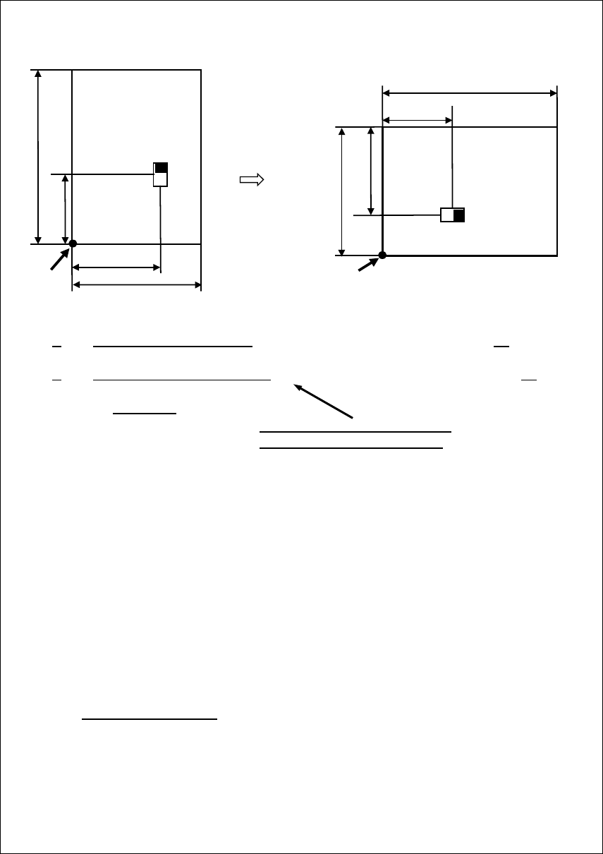
* The bottom-side placement coordinates are defined in the coordinate system viewed from
the top side as shown in the following figure, transformation is required.
Origin as viewed from the top side
●
●
◎
◎
◎
5
5
95
45
150
This point becomes an origin as
viewed from the bottom side.
Consequently, it becomes as shown below.
At this time, the expression is as follows:.
X = [-X] + [0] + [1]X-Board + [-10] = -95+0+150-10 = 45
When converting the placement data, it is defined that numeric data should be converted by
user-defined wizard but no data exists in the file to be actually converted. In this case, 0 is set
as the default value in the field of the output file.
Length from the end face of PWB to the
former origin (5) + Length from the end face
to the new origin (5)
X coordinates after
transformation
CAD
coordinates
PWB outer
dimensions
47
<Exercise 3>
*
When a lengthways-shape component is clamped as a long sideway shape at production, it
is necessary to convert PWB data and placement data. For the placement data, the
placement coordinates and placement angle must be converted. Now, try to convert the
placement data.
Origin
Origin
150
70
100
150
60
180°
270°
70
100
The placement data is converted as follows:
X = [0] + [Y] + [0]X-Board+ [0] ← X=0 + 60 + 0 + 0 = 60
Y = [0] + [-X] + [0]Y-Board+ [100] ← Y=0 + -70 + 0 + 100 = 30
Theta = ( [T] + [270] ) %360
"100" is the original PWB outer
dimensions in the X direction.
* In the above, "%360" means an arithmetic operation to put the answer within the range of
0 to 359.95 by subtracting 360 from the calculated result when the calculated result in
parentheses exceeds 360º.
In the above calculation for the placement point:
(270 + 270) %360
= (540)%360 = 540 – 360 = 180
* In addition, it is necessary to make a change according to 0º to 359.95º to be used for the
JUKI production program when there is minus data exists, for example, when the
placement angle is defined as -180º to 180º in the CAD data.
The expression is as follows:
θ = ([θ] + [360]) %360
Regarding the PWB layout offset and PWB outer dimensions, they must be changed.
• Changing the PWB layout offset
→ Refer to "7.3.2. Custom transformation settings (PWB) screen ".
• Changing the PWB outer dimensions
→ When changing the PWB outer dimensions, change it in the data change dialog
box.