FLEXLINE-CAD_INM.pdf - 第120页
B-4 T ransform ation t ake s place when any of the following parameters changes : 1. PCB Transpor t direction “ Left to Right ” is changed to “ Right to Left. ” 2. PCB transport ref erence “ Front ” is c hanged to “ Rear…
B-3
3.2 Transforming Flexline CAD coordinate system to machine coordinate
system
Again, machines use different ways to transform the PCB reference coordinate (positioning hole
positions or PCB layout offset) based on the PCB transport reference (front or rear) and PCB
transport direction (right to left or left to right).
The equations used in each transformation are as follows:
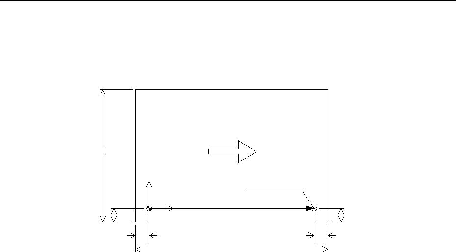
KSx
Hx
Hy
KSy
Transportation direction
Tx
Y
X
Positionong hole
Ty
Positioning hole coordinate
Figure B-2: Machine coordinate system where transport direction is
(“Left to Right”) and front reference
The following symbols are used in expressing transformation equations as described later:
• X X-coordinate of PCB.
• Y Y-coordinate of PCB.
• KSX X-dimension of PCB.
• KSY Y-dimension of PCB.
• LX X-layout offset of PCB (before transformation).
• LY Y-layout offset of PCB (before transformation).
• LX ′ X-layout offset of PCB (after transformation).
• LY ′ X-layout offset of PCB (after transformation).
• HX See figure shown above.
• HY See figure shown above.
• PX X-coordinate of PCB pin or edge reference point (before transformation).
• PY Y-coordinate of PCB pin or edge reference point (before transformation).
• PX ′ X-coordinate of PCB pin or edge reference point (after transformation).
• PY ′ Y-coordinate of PCB pin or edge reference point (after transformation).
• TX constant = 5 MM if pin reference is used (PCB X-margin) or constant = 0 if
edge reference is used.
• TY constant = 5 MM if pin reference is used (PCB Y-margin) or constant = 0 if
edge reference is used.
B-4
Transformation takes place when any of the following parameters changes:
1. PCB Transport direction
“Left to Right” is changed to “Right to Left.”
2. PCB transport reference
“Front” is changed to “Rear.”
• PCB layout offset changes according to the following equations:
• Transport direction is changed to “Right to Left”
LX ′ = LX - KSX
• Reference is changed to “Rear reference”
LY ′ = KSY + LY
1. Changing PCB transport direction:
• PCB pin or edge reference changes according to the following conditions and equations:
Front reference:
Left to Right transport direction is changed to Right to Left transport direction:
PX ′ = - ((KSX - HX) - TX)
Right to Left transport direction is changed to Left to Right transport direction:
PX ′ = + ((KSX - HX) - TX)
Rear reference:
Right to Left transport direction is changed to Left to Right transport direction:
PX ′ = + ((KSX - HX) - TX)
Left to Right transport direction is changed to Right to Left transport direction:
PX ′ = - ((KSX - HX) - TX)
2. Changing PCB transport reference:
• PCB pin or edge reference changes according to the following conditions and equations:
Left to Right direction:
Front reference is changed to Rear reference:
PY ′ = + ((KSY - HY) - TY)
Rear reference is changed to Front reference:
PY ′ = - ((KSY - HY) - TY)
Right to Left direction:
Front reference is changed to Rear reference:
PY ′ = + ((KSY - HY) - TY)
Rear reference is changed to Front reference:
PY ′ = - ((KSY - HY) - TY)
C-1
Appendix C Default Format
♦
Simple Text Format (STF)
Simple Text Format is a format developed for users needing production files for older style JUKI
machines. STF works in two different ways:
1) If you need to convert a production file from an newer JUKI machine to an older JUKI
machine, Flexline CAD can generate a Simple Text Format to be read by Version 3.62 of
FlexProgram (old CAD conversion system) so that it can be used in the older machines.
2) Because of the simplicity of STF, a user can also use it as an input format. The schema for
STF is as follows:
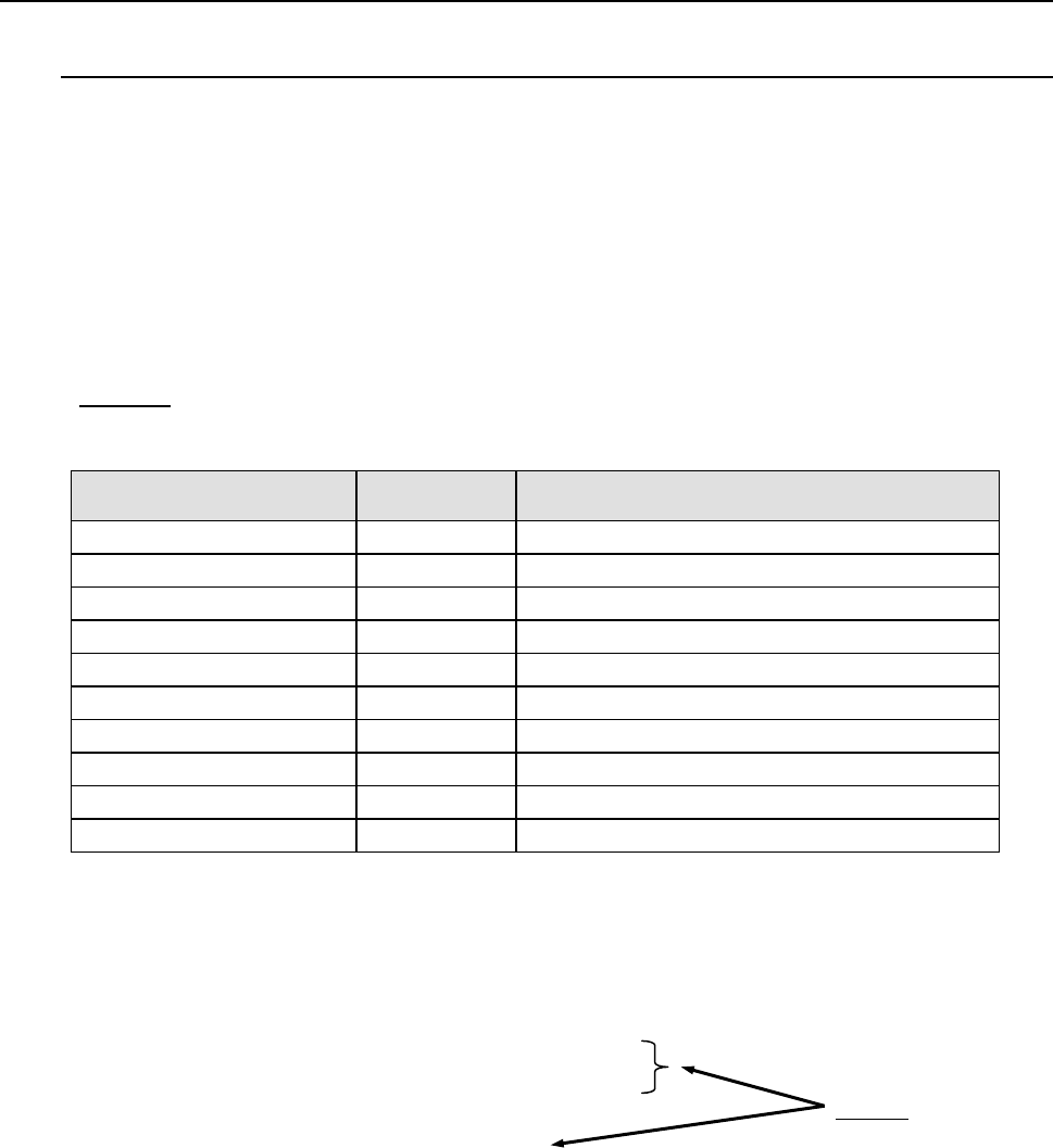
* Schema: Describes the order of field arrangement. This is used as the basis for Flexline
CAD to recognize CAD data.
Data item
Schema
identifier
Tag
PCB ID
Id
Comment lines tagged with PCB FIELDS
PCB reference coordinate X
Ref-x
Comment lines tagged with PCB FIELDS
PCB reference coordinate Y Ref-y Comment lines tagged with PCB FIELDS
BOC position 1X to 3X Boc-x Comment lines tagged with PCB FIELDS
BOC position 1Y to 3Y
Boc-y
Comment lines tagged with PCB FIELDS
Placement position X
X
Comment lines tagged with PLACEMENT FIELDS
Placement position Y
Y
Comment lines tagged with PLACEMENT FIELDS
Placement angle Y Rotation Comment lines tagged with PLACEMENT FIELDS
Placement ID
Id
Comment lines tagged with PLACEMENT FIELDS
Component name
Name
Comment lines tagged with PLACEMENT FIELDS
The following is a Simple Text Format data file that is compatible with Version 3.62 of
FlexlineProgram. Line 3, line 4, and line 6 correspond to the schema.
! SIMPLE TEXT FORMAT VERSION 1.0
!
! PCB FIELDS - id, ref-x, ref-y, boc-x, boc-y, boc-x, boc-y,
! boc-x, boc-y,
! Schema
! PLACEMENT FIELDS - x, y, rotation, id, name,
!
Single Board id, 140.000, 0.000, 130.000, 120.000, 1.000, 2.000, 3.000, 4.000
12.000, 12.000, 0.000,F1,COMP #1,
33.000, 33.000, 0.000,F2,COMP #2,
55.000, 55.000, 0.000,F3,COMP #3,