FLEXLINE-CAD_INM.pdf - 第113页
A- 16 10. Checki ng the conversi on resul t As an example, check the contents of "T utorialT .iss" by using IS V ersion 2.0. ① S tart the I S program editor and select the "File" - " Open" c…
A-15
9. Converting the file
Convert a file by using the created input format “Tutorial.”
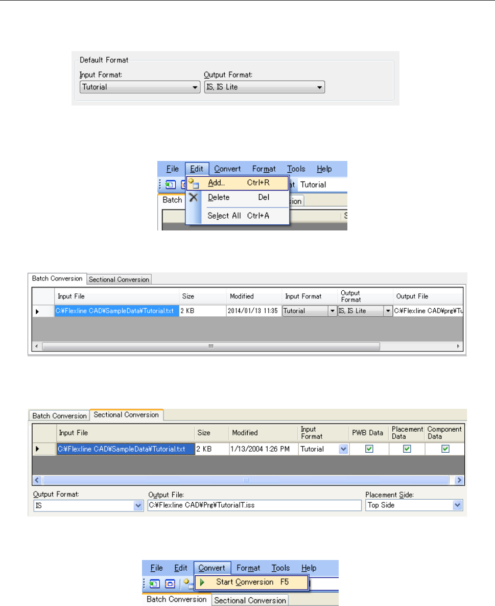
① On the “Default Format” screen of “Set Environments": select “Tutorial” for the “Input format",
and “IS,IS Lite” for the “Output format."
Figure A-21 Selection of formats
② Select the "Edit" - "Add" command or click the "Add" button of the tool bar to open the "Open"
dialog box.
Figure A-22 "Edit" - "Add" menu
③ In the "Open" dialog box, select the {Flexline CAD install folder}\SampleData\Tutorial.txt and
add the file to the file table.
Figure A-23 Batch conversion file table
* When the file table is the "Sectional conversion" screen, check off the "PWB," "Placement,"
and "Component."
Figure A-24 Sectional conversion file table
④ Select the "Convert" - "Start Conversion" command or click the "Start Conversion" button of
the tool bar to start the conversion.
Figure A-25 "Convert" - "Start Conversion" menu
⑤ The message "Conversion is completed" is displayed. This completes the conversion.
The converted files consist of two files: "TutorialT.iss" and "TutorialB.iss.”
"TutorialT.iss" → File created with the placement data of the top side of "Tutorial.txt"
TutorialB.iss" → File created with the placement data of the bottom side of "Tutorial.txt"
A-16
10. Checking the conversion result
As an example, check the contents of "TutorialT.iss" by using IS Version 2.0.
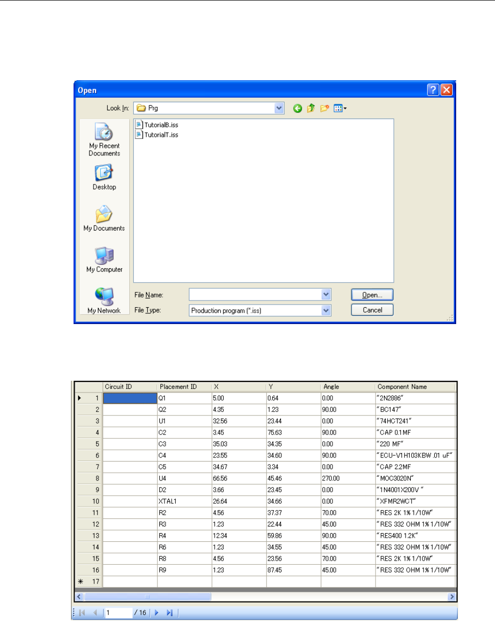
① Start the IS program editor and select the "File" - "Open" command. In the displayed "Open"
dialog box, select "TutorialT.iss."
Figure A-26 "Open" dialog box of the program editor
② Check the PWB data, placement data, and component data. The following figure shows a
screen of placement data.
Figure A-27 Placement data screen of the program editor
Some component names are enclosed with """. In this case, perform conversion by
specifying """ for "Quotation mark" on the "Global Setup" screen of the user-defined wizard.
Thus, """ is removed after conversion.
A-17
* Define non-matrix boards
To define a non-matrix board in the User-defined Format Wizard, the circuit position data
needs to be stored as a table or array data in the input file. Each circuit position must be on a
separate line.
[Example]
Define a non-matrix board as follows:
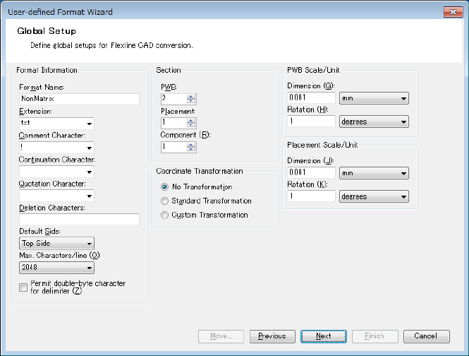
1. Since you cannot define the non-matrix PWB position data and other PWB related data in
the same PWB section, you need to specify 2 PWB sections at the beginning.
Figure A-28 Global Setup screen
Click the "Next" button.