FLEXLINE-CAD_INM.pdf - 第33页
28 Figure 5. 1 - 3 Setting change from the l ist In the batch conv ersion m ode, multiple files are converted collectiv ely (individual setting can be performed) according to its literal sense. For example, conversion is…
27
Chapter 5 Batch Conversion and Sectional Conversion *1
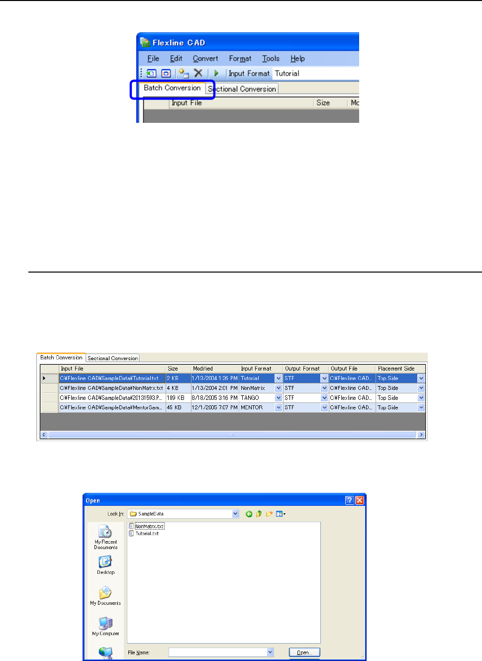
The conversion mode can be selected by selecting the "Batch conversion" tab or "Sectional
conversion" tab of the main screen.
Figure 5-1 Selection of conversion mode
The column width of the file table can be freely adjusted. Put the mouse cursor to the boundary
on the right side of each column header. When the cursor shape is changed into left and right
two lines of the arrow, drag the boundary. Thus, the column width can be narrowed or
extended.
*1 The screen displayed with the Version 5.10 or earlier is different from that with the Version
6.00 or later.
5.1 Batch conversion mode
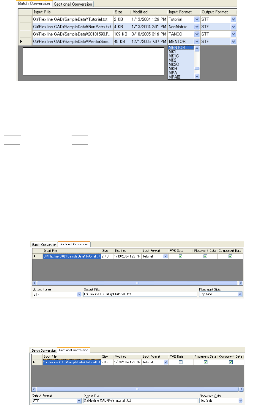
Select the "Batch conversion" tab on the main screen. At this time, one or multiple CAD data
can be converted simultaneously. For example, if four input files are added to the batch
conversion file table and conversion is started, all the input files are converted sequentially from
the top. During conversion, the selected line of the conversion file table is shifted to indicate the
file being processed.
Figure 5.1-1 Batch conversion file table
Regarding "Input file" or "Output file", double-click the cell or select the cell and then press the
"Enter" key. Then, the following dialog box is displayed to change the file.
Figure 5.1-2 "Open file" dialog box
28
Figure 5.1-3 Setting change from the list
In the batch conversion mode, multiple files are converted collectively (individual setting can be
performed) according to its literal sense.
For example, conversion is performed as follows:
File A → Converted into File X
File B → Converted into File Y
File C → Converted into File Z
5.2 Sectional conversion mode
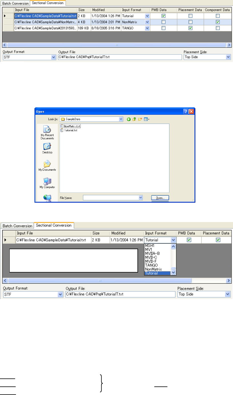
Select the "Sectional conversion" tab on the main screen. When PWB data, placement data,
and component data are distributed to multiple files, it is possible to create a single output file
through combination of each data.
It is also possible to convert only a part of PWB data, placement data, and component data from
one CAD data.
• Screen example where one file is selected:
Figure 5.2-1 Sectional conversion file table (for one file)
• Changing only a part from a single file:
In this example, placement and component data are converted but PWB data is not
converted.
Figure 5.2-2 Sectional conversion table
(only placement data and component data are selected)
Regarding "Input format", "Output format", and
"Placement side", click the cell to display a list and
then change values.
29
• Screen example where multiple files are selected:
Figure 5.2-3 Sectional conversion file table (for multiple files)
Regarding "Input file" or "Output file", double-click the cell or text box or select the cell or text
box and then press the "Enter" key. Then, the following dialog box is displayed to change the
file.
Figure 5.2-4 "Open file" dialog box
F
Figure 5.2-5 Setting change from the list
For "PWB data", "placement data", and "component data", only one can be checked off in each
column. If another cell is selected in the checked-off column, the later selected cell is checked
off.
In the sectional conversion mode, multiple partial files are converted into a single file.
Accordingly, even if multiple input files are added, they are always converted into a single file.
For example, conversion is performed as follows:
File A (file of PWB data only)
File B (file of placement data only) → Converted into file T
File C (file of component data only)
“Input format” ”Output format” “Placement side” are
appeared by clicking the cell. Then change the value
by selecting the list.