FLEXLINE-CAD_INM.pdf - 第139页
C- 19 Speci f y the GERBER file formats After reading a dat a f ile, select the “ Convert ” – “ S tart Conv ersion ” command from the menus, or click the “ S tart Conversion ” butt on of the toolbar; the “ Gerber file fo…
C-18
♦
“GERBER” *1
The “GERBER” format has two types, RS-274D and RS-274X.
RS-274D is called “Standard Gerber” and RS-274X is called “Extended Gerber”.
* Flexline CAD accepts the Standard Gerber (RS-274D) only. The Extended Gerber (RS-274X)
cannot be recognized.
* The character code for the Gerber file is ASCII.
◇Data field that can be converted
PWB data
Placement data
Component data
-
Placement Position X
-
-
Placement Position Y
-
“GERBER” sample
*
G54D10*
G75*
G54D12*
X76500Y108500D02*
G55D03*
X93500Y108500D02*
G55D03*
X76500Y91500D02*
G55D03*
X93500Y91500D02*
G55D03*
X93500Y85500D02*
G55D03*
X76500Y85500D02*
G55D03*
X76500Y68500D02*
G55D03*
X93500Y68500D02*
G55D03*
X20500Y107500D02*
G55D03*
X61500Y107500D02*
G55D03*
X61500Y66500D02*
G55D03*
X20500Y66500D02*
……
X147975Y31275D01*
X0Y0D02*
M00*
*1 Enabled with the Version 6.00 or later only. (Some functions may be enabled with the latest
version only.)
C-19
Specify the GERBER file formats
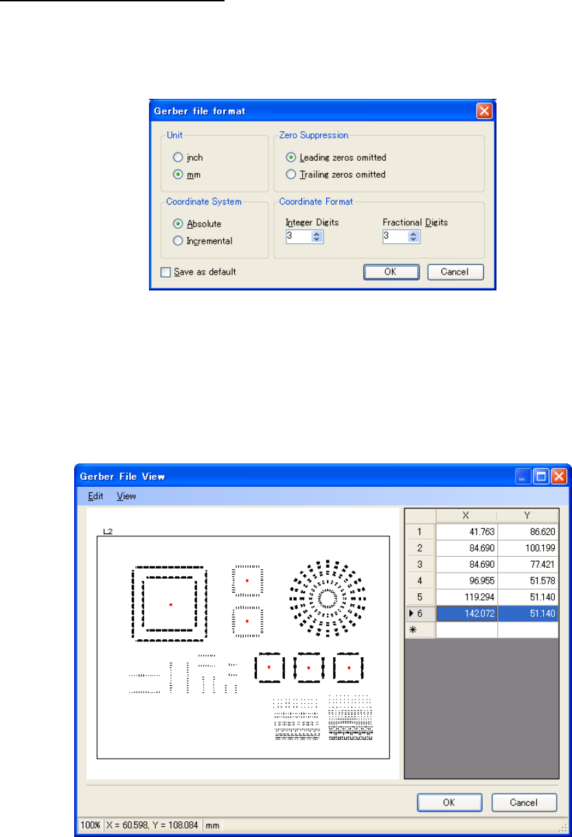
After reading a data file, select the “Convert” – “Start Conversion” command from the menus, or
click the “Start Conversion” button of the toolbar; the “Gerber file format” dialog box appears.
The settings in this dialog box are used to convert the data when the Gerber file does not
specify them.
Figure C-3 Gerber file format
The input range for the “Integer Digits” and “Fractional Digits” is 0 to 6. If the coordinate value
has more digits than this format, the extra digits are automatically discarded.
To save the settings on the “Gerber file format” dialog box, check the box of “Save as default”
and click the “OK” button.
Once the “OK” button is clicked, it starts to convert the Gerber file. When the conversion is
finished, the “Gerber File View” dialog box appears.
Figure C-4 Gerber File View
The “Gerber File View” dialog box displays the list of the placement points and the image of the
board according to the data.
The “OK” button is disabled by default, but can be enabled by adding a placement point.
The status bar at the bottom of the dialog box shows from left: the display magnification, the
C-20
coordinates pointed by the mouse and the unit of the coordinates. The unit of the coordinates is
the one specified last in the Gerber file; however, if the Gerber file does not specify the unit, a
unit specified on the “Gerber File View” dialog box is used.
Clicking on the image of the board allows you to add a placement point.
A red mark is placed on the clicked point, and the coordinates are added to the list
automatically. Also, you can type a value of the coordinate directly in the list, which is editable.
Up to 6 digits can be entered for the integer portion of the value. The number of the digits for the
fractional portion depends on the setting of the “Gerber File Format” dialog box; the extra digits
are automatically discarded.
To delete a placement point, specify the row, and then select the “Edit” – “Delete” command
from the menus or press the [Delete] key.
To specify all rows, select the “Edit” – “Select All” command from the menus or press the [Ctrl]
key and the [A] key at the same time.
To enlarge the image of the board, select the “View” – “Zoom In” command from the menus or
press the [Ctrl] key and the [+] key at the same time.
To reduce the image of the board, select the “View” – “Zoom Out” command from the menus or
press the [Ctrl] key and the [-] key at the same time.
Press the “OK” button to continue the conversion using the selected placement data.