FLEXLINE-CAD_INM.pdf - 第40页
35 6.4 Vi ew ing Conver sion Logs *1 Execute one of the following operations of (1) and (2). (1) Select the "File" - "View Conv ersion Logs" menu. Figure 6. 4 - 1 “ File ”- “ V iew Conversion Logs ” m…
34
6.3 Converting CAD data
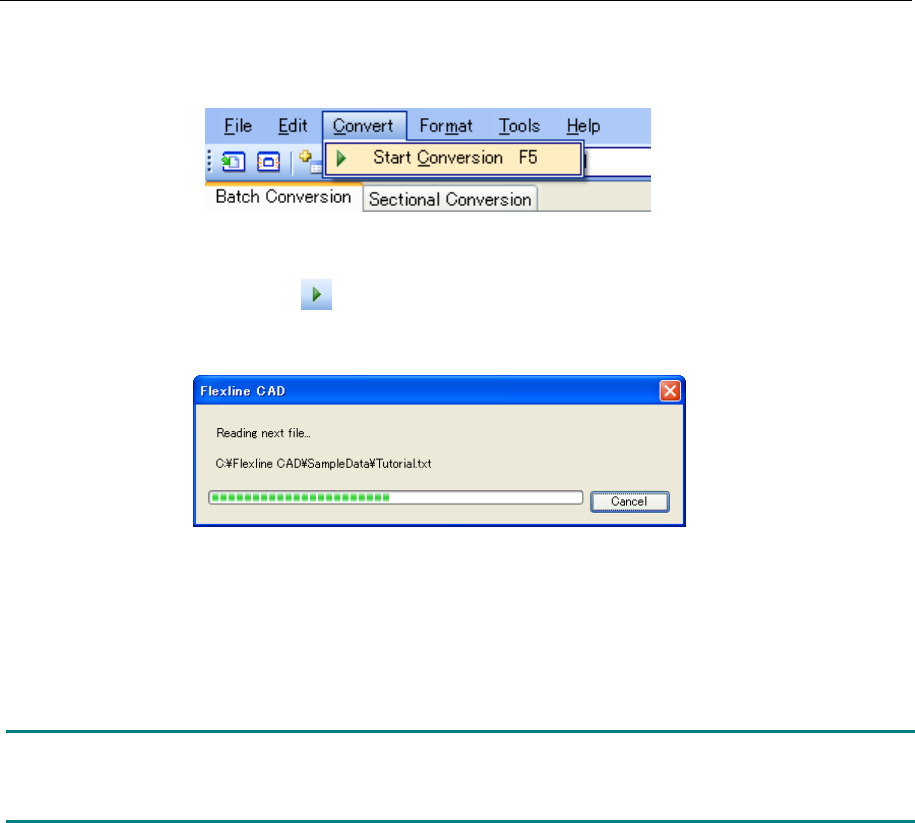
Execute either one of the following operations of (1) and (2).
(1) Select the "Convert" - "Start conversion"
Figure 6.3-1 "Convert" - "Start conversion" menu
(2) Click "Start conversion" ( ) of the tool bar.
Conversion is started and a dialog box to indicate the progress of conversion is displayed.
Figure 6.3-2 Progress status dialog box
The converted file is saved into the path specified in "Output file" of the file table. (The output
file saving destination and the output file name can also be changed. However, its explanation
is omitted.)
Note: If the decimal-place digits of the numeric value set in CAD data are different from the
corresponding unit of the output format, conversion is performed according to the unit of
numeric value of the corresponding model of the output format.
35
6.4 Viewing Conversion Logs *1
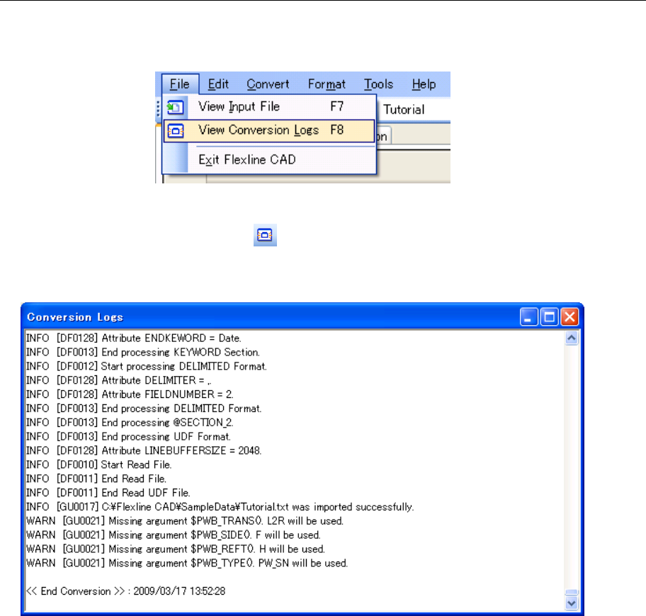
Execute one of the following operations of (1) and (2).
(1) Select the "File" - "View Conversion Logs" menu.
Figure 6.4-1 “File”- “View Conversion Logs” menu
(2) Click the "View Conversion Logs" ( ) of the tool bar.
The last line of the conversion logs is displayed on the “Conversion Logs” screen.
Figure 6.4-2 “Conversion Logs” screen
While viewing the “Conversion Logs” screen, you can operate the Flexline CAD.
If you convert data while viewing the “Conversion Logs” screen, the conversion logs are updated
automatically and the last line of the conversion logs is displayed.
*1. The screen displayed with the Version 5.10 or earlier is different from that with the Version 6.00
or later.
36
Chapter 7 User-Defined Wizard
Flexline CAD functions only when information is defined by a certain method. Description must
be performed so that Flexline CAD can recognize the positions and formats of PWB (printed–
wiring board) information, placement information, and component information.
There are various CAD formats. For Flexline CAD, a part of these formats is available but all of
them are not applicable. For a CAD format that is not prepared in Flexline CAD, a format
matched to this CAD data format must be created by using the "user-defined wizard".
This chapter describes the creation of a new input format by the user-defined wizard and the
definitions of PWB data, placement data, and component data.
Note:
The user-defined wizard is applicable to various format types but cannot define every format
type. For formats that cannot be specified by the specifying method prepared in the user-
defined wizard, definition is impossible.
<Example>
- There is no delimiter in each field. → Delimiter cannot be selected.
- The length of each field (X coordinate, Y coordinate, etc.) varies depending on each line. →
Fixed length cannot be used.
N5X0Y0W0Z1PN(CPG16GST101J )C()M000001T0/7;
N6X24240Y29040W0Z1PN(CQG16GST101J )C(R103 )M000000T0/0;
N7X26280Y29040W0Z1PN(CRD16GST101J )C(R102 )M000000T0/0;
N10X23520Y26400W180Z2PN(GRN36F103Z50PT )C(C103 )M000000T0/0;
N11X26880Y26400W0Z2PN(GRN36F103Z50PT )C(C101 )M000000T0/0;
Check the contents of CAD data
by the note pad program and
determine a definition method.
Start the User
-Defined Format
Wizard.
Set the CAD Specific screen.
Set the Transformation screens.
Set the Section Definition screen.
Set the Field Definition screen.
Set the Field Transformation screen.
Specify the format name, number of sections, unit
of numeric values, etc.
Enter
parameters for the case
s where numeric
values must be re-calculated based on certain
criteria.
Specify the section layout and field layout methods.
Define each field.
Used when detail definition of fields is required.
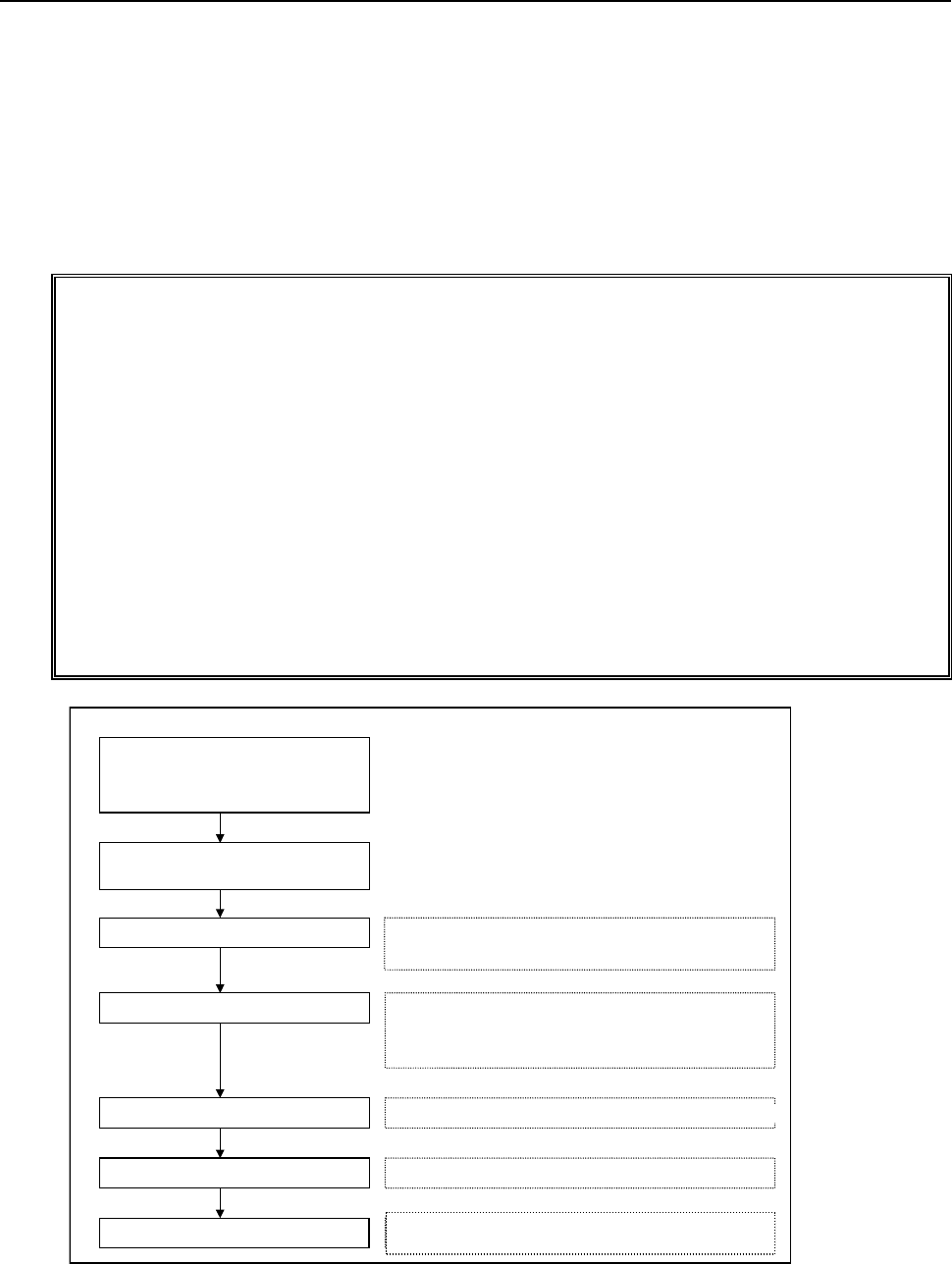
Figure 7-1 User-defined wizard flowchart
Check the contents of CAD data
by the note pad and determine a
defining
method
Start the user-defined wizard
Set the global setup screen
Set the conversion screen
Set the section definition screen
Set the field definition screen
Set the field conversion screen
Specify the format name, number of sections, unit of
numeric values, etc.
Set this screen when numeric values must be
collectively con
verted on the basis of a certain
reference at conversion.
Specify section layout method and field layout method.
This screen is used when a detail definition of field is
required.