FLEXLINE-CAD_INM.pdf - 第53页
48 7.4 Section definition screen Define each section data list of PW B, placement, and component defined in the "Global Setup" screen. Figure 7. 4 - 1 Sect ion Defin ition * W hen multiple P W B sections are se…
47
<Exercise 3>
*
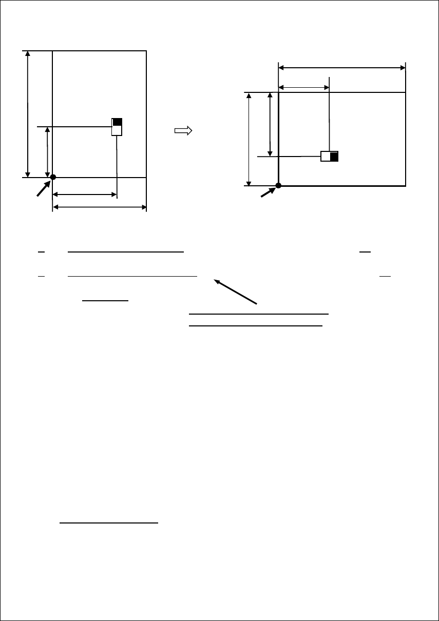
When a lengthways-shape component is clamped as a long sideway shape at production, it
is necessary to convert PWB data and placement data. For the placement data, the
placement coordinates and placement angle must be converted. Now, try to convert the
placement data.
Origin
Origin
150
70
100
150
60
180°
270°
70
100
The placement data is converted as follows:
X = [0] + [Y] + [0]X-Board+ [0] ← X=0 + 60 + 0 + 0 = 60
Y = [0] + [-X] + [0]Y-Board+ [100] ← Y=0 + -70 + 0 + 100 = 30
Theta = ( [T] + [270] ) %360
"100" is the original PWB outer
dimensions in the X direction.
* In the above, "%360" means an arithmetic operation to put the answer within the range of
0 to 359.95 by subtracting 360 from the calculated result when the calculated result in
parentheses exceeds 360º.
In the above calculation for the placement point:
(270 + 270) %360
= (540)%360 = 540 – 360 = 180
* In addition, it is necessary to make a change according to 0º to 359.95º to be used for the
JUKI production program when there is minus data exists, for example, when the
placement angle is defined as -180º to 180º in the CAD data.
The expression is as follows:
θ = ([θ] + [360]) %360
Regarding the PWB layout offset and PWB outer dimensions, they must be changed.
• Changing the PWB layout offset
→ Refer to "7.3.2. Custom transformation settings (PWB) screen ".
• Changing the PWB outer dimensions
→ When changing the PWB outer dimensions, change it in the data change dialog
box.
48
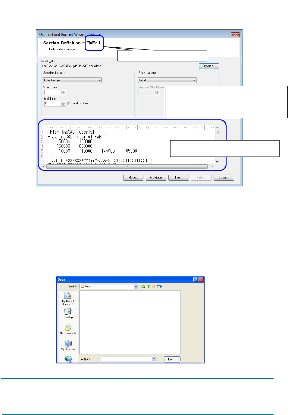
7.4 Section definition screen
Define each section data list of PWB, placement, and component defined in the "Global Setup"
screen.
Figure 7.4-1 Section Definition
* When multiple PWB sections are set, the "Section Definition" screens corresponding to the
set number are displayed.
7.4.1 Reading the file
First, select a data file of the format that is created.
On the above screen, click the "Browse" button to display the following dialog box. Select a file
and click the "Open" button. The selected file is read.
Figure 7.4.1-1 "Open file" dialog box
Note: In case the file includes Japanese characters, this file is acceptable only when the
following conditions are satisfied. (For Japanese version only)
- Japanese exists in the data field of the data file.
- The delimiter is a Japanese character.
The contents of the input file selected by
"Browse" are displayed.
<Setting order in the section definition screen>
①
Read the file ("Refer")
②
Specify the section layout.
③ Specify the field layout.
The section to be defined is displayed.
49
7.4.2 Section layout
Select a specifying method to specify the portion of PWB data, placement data, and component
data in the whole CAD data. As specifying methods, the "Section," "Tag," and "Line range" are
available.
In the following example, PWB data can be defined in the "Line range," placement data can be
defined in the "Tag," and component data can be defined in the "Section."
7.4.2.1. Section
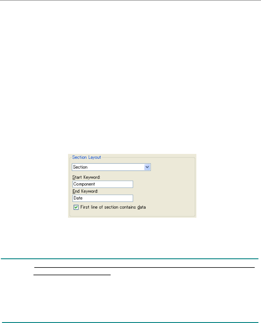
When data exists between the start keyword and the end keyword, this section is used.
When the "Section" is selected from the pull-down menu, the keyword input screen is displayed.
◊ The portion defined in the "Section" is read even if there are multiple portions in the
production program. When the end keyword is blank, all the portions subsequent to the
start keyword are converted.
◊ Regarding the option of "Data exists in the first line of the section," it can be selected when
the section layout is the "Section" and the field layout is the "Fixed length" or "Delimited." If
this is option is checked off, this prevents unnecessary data from being written into the
output file when no data exists in the first line of the section.
Figure 7.4.2-1 Section Layout (Section)
In this example, all the lines between the "Component" and "Date" are specified as component
data. (Both start line and end line are included.)
Note: Regarding the keyword, there is a distinction between upper-case characters
and lower-case characters.
Do not use the symbol specified as a comment character for the keyword.
(For the definition of comment character, refer to "7.2.1 Format information.")
Enter specific characters for the keyword. In the above example, when "PLC" is entered as
the start keyword, the first "PLC" appearing from the top of the file is used as the start
keyword though "PLC" appears repeatedly in the file. The keyword can be recognized
regardless of its position.