FLEXLINE-CAD_INM.pdf - 第138页
C- 18 ♦ “GERBER” *1 The “ GERBER ” format has t wo ty pes, RS - 274D and RS - 274X. RS - 274D is called “ S tandard Gerber ” and RS - 274X is called “ Extended Gerber ”. * Flexline CAD accepts the S tandard Ger ber (RS -…
C-17
Selecting Placement Blocks to Convert
After the data file is read, select the "Convert" - Start conversion" command or click the "Start
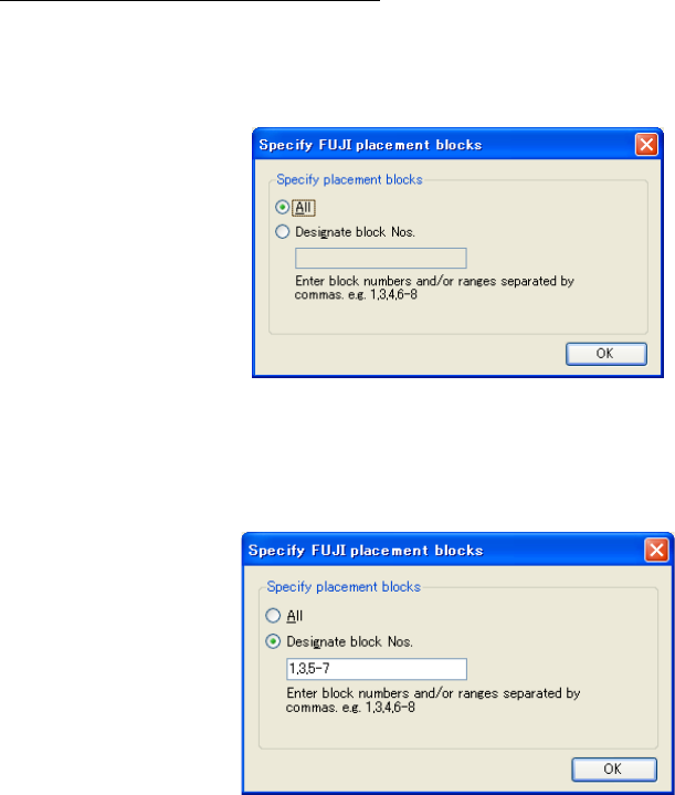
conversion" button of the tool bar to display the "Specify FUJI placement blocks" dialog box.
The default is set to the "All."
Figure C-1 Specify FUJI placement blocks (All)
After selecting the "Designate block Nos.," the text box can be used. Enter block numbers. Only
an integer of 0 to 255 can be entered as the block number. For multiple numeric values, specify
them by separating each of them by "," (comma) or specify the range by using "-" (hyphen).
Figure C-2 Designate FUJI placement blocks (Designate block Nos.)
When you click the "OK" button, the conversion starts.
C-18
♦
“GERBER” *1
The “GERBER” format has two types, RS-274D and RS-274X.
RS-274D is called “Standard Gerber” and RS-274X is called “Extended Gerber”.
* Flexline CAD accepts the Standard Gerber (RS-274D) only. The Extended Gerber (RS-274X)
cannot be recognized.
* The character code for the Gerber file is ASCII.
◇Data field that can be converted
PWB data
Placement data
Component data
-
Placement Position X
-
-
Placement Position Y
-
“GERBER” sample
*
G54D10*
G75*
G54D12*
X76500Y108500D02*
G55D03*
X93500Y108500D02*
G55D03*
X76500Y91500D02*
G55D03*
X93500Y91500D02*
G55D03*
X93500Y85500D02*
G55D03*
X76500Y85500D02*
G55D03*
X76500Y68500D02*
G55D03*
X93500Y68500D02*
G55D03*
X20500Y107500D02*
G55D03*
X61500Y107500D02*
G55D03*
X61500Y66500D02*
G55D03*
X20500Y66500D02*
……
X147975Y31275D01*
X0Y0D02*
M00*
*1 Enabled with the Version 6.00 or later only. (Some functions may be enabled with the latest
version only.)
C-19
Specify the GERBER file formats
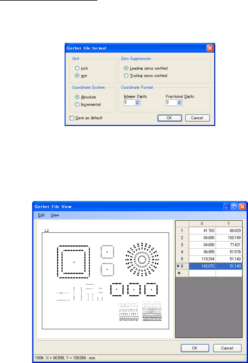
After reading a data file, select the “Convert” – “Start Conversion” command from the menus, or
click the “Start Conversion” button of the toolbar; the “Gerber file format” dialog box appears.
The settings in this dialog box are used to convert the data when the Gerber file does not
specify them.
Figure C-3 Gerber file format
The input range for the “Integer Digits” and “Fractional Digits” is 0 to 6. If the coordinate value
has more digits than this format, the extra digits are automatically discarded.
To save the settings on the “Gerber file format” dialog box, check the box of “Save as default”
and click the “OK” button.
Once the “OK” button is clicked, it starts to convert the Gerber file. When the conversion is
finished, the “Gerber File View” dialog box appears.
Figure C-4 Gerber File View
The “Gerber File View” dialog box displays the list of the placement points and the image of the
board according to the data.
The “OK” button is disabled by default, but can be enabled by adding a placement point.
The status bar at the bottom of the dialog box shows from left: the display magnification, the