FLEXLINE-CAD_INM.pdf - 第73页
68 8.2 PWB dat a screen 8.2.1 Basic set tings screen W hen "Single PW B" is selected in the "PW B Configuration," the " Mark is light" and "Mark is dark" in the "Bad Mark type…
67
8.1 General
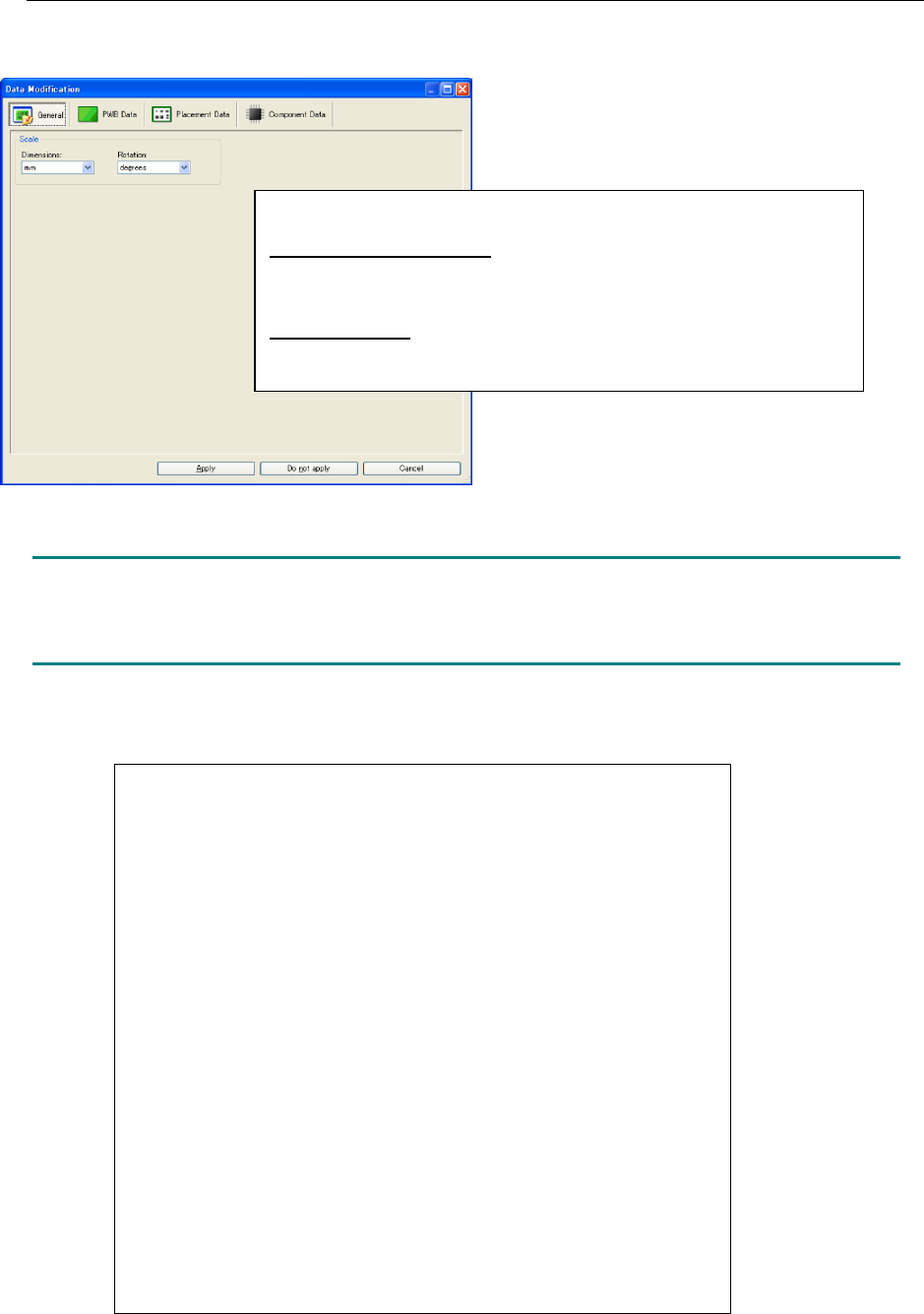
When the data modification dialog box is displayed, the general screen is displayed in the first
place.
Figure 8.1-1 General
NOTE:
After the display unit is changed in the data modification dialog box, the data is recalculated.
Note that the data accuracy may be somewhat lost depending on the source data.
The coefficients of conversion used in Flexline CAD are as follows:
<Unit change of the data displayed in the data modification dialog box>
Initial value of display unit: It is the unit set in input format when value
set in "Change" - "Unit of default" in environment setup is "Auto".
It is the unit when setting value is things except "Auto".
JUKI type format: Dimension "mm" and rotation "degrees"
At the end of the data modification dialog box, the units of all the data
are recalculated in "mm" for dimension and "degrees" for rotation.
1 Inch = 1000 mils
1 Inch = 25.4 mm
1 Inch = 2540 (x) 1/100 mm
1 Inch = 2.54 cm
1 mil = 0.001 inches
1 mil = 0.0254 mm
1 mil = 2.54 (x) 1/100 mm
1 mil = 2.54 / 1000 cm
1 mm = 3.93700287401576E-02 inches
1 mm = 39.3700787401575 mils
1 mm = 100 (x) 1/100 mm
1 mm = 1 / 10 cm
1/100 mm = 3.93700287401576E-04 inches
1/100 mm = 0.393700787401575 mils
1/100 mm = 1 / 100 mm
1/100 mm = 1 / 1000 cm
1 cm = 1 / 2.54 inches
1 cm = 1000 / 2.54 mils
1 cm = 10 mm
1 cm = 1000 (x) 1/100 mm
68
8.2 PWB data screen
8.2.1 Basic settings screen
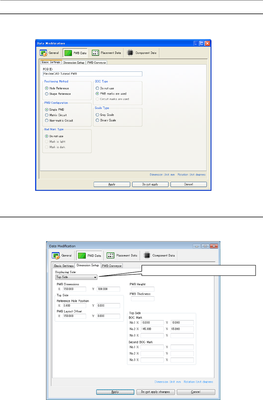
When "Single PWB" is selected in the "PWB Configuration," the " Mark is light" and "Mark is
dark" in the "Bad Mark type," and "Circuit marks are used" in the "BOC type" cannot be
selected.
Figure 8.2.1-1 Basic Settings of PWB data
8.2.2 Dimension Setup screen (Single PWB)
When the "Do not use" is selected in the "BOC type" in the basic settings, the BOC mark
position is not displayed. When the format supports the second BOC mark, the BOC mark
position and the second BOC mark position are displayed.
Figure 8.2.2-1 Dimension setup of PWB data (Single )
The PWB top/bottom side display is switched.
69
8.2.3 Dimension Setup screen (Matrix Circuit)
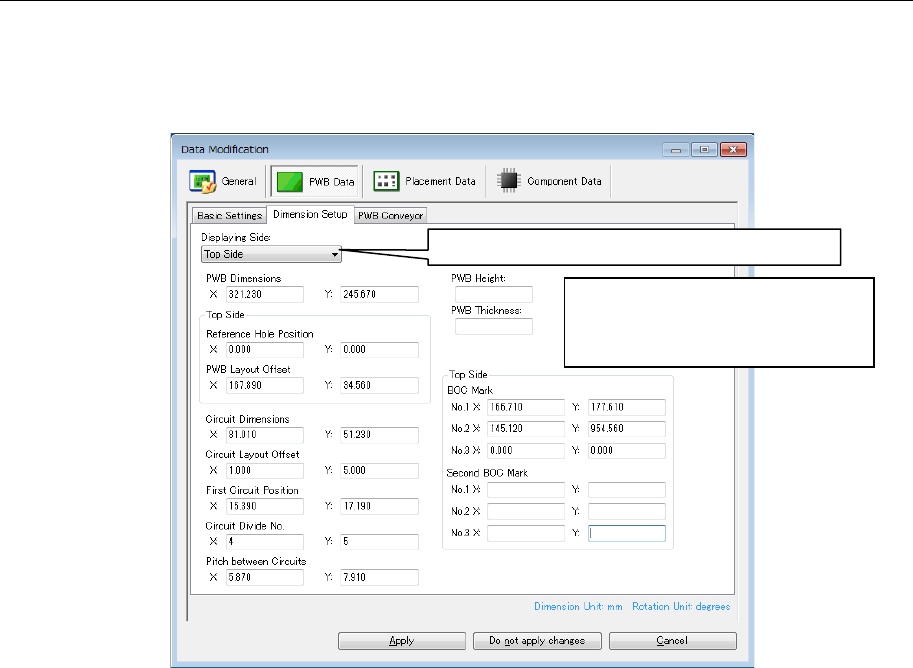
When the "Do not use" is selected in the "BOC type" in the basic settings, the BOC mark
position is not displayed. When the format supports the second BOC mark, the BOC mark
position and the second BOC mark position are displayed.When the "Do not use" is selected
in the "Bad Mark Type" in the basic settings, the bad mark position is not displayed.
Figure 8.2.3-1 Dimension Setup of PWB data (Matrix Circuit)
The PWB top/bottom side display is switched.
When the number of circuits
exceeds the upper limit on the
output format, the number of circuit
divisions is displayed in red.