FLEXLINE-CAD_INM.pdf - 第11页
6 The following figure shows a conversion operation flow for using the CAD conv ersion proce ss: 入力フォーマットがあるか CAD データ の中身が 入力フォーマットを作成できる 構成に なっているか 入力フォーマットを作成 する はい いいえ ファイルの読み込み データ 変更 ダイアログ を 表示 する 設定である データ 変更 ダイア…
5
Chapter 2 Outline of Operations
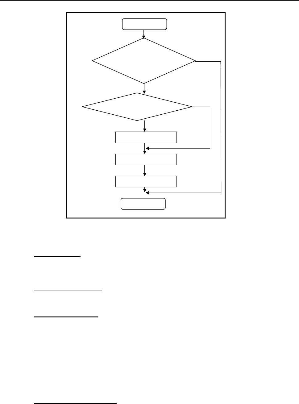
An outline of data conversion is shown below:
Conversion
Are the contents of CAD
data configured so as to
create an input format?
Is the input format available?
Create an input format
File output
No
Yes
No
Yes
CAD data
End
Figure 2-1 General data conversion flowchart of Flexline CAD
◇The items required to use Flexline CAD are as follows:
1. "Input format"
This means an input format that indicates the data sequence of the CAD data to be
converted. Define the input format before CAD conversion and select a format for a file
(CAD data, etc.) to be converted at conversion. Thus, the CAD data file is converted.
2. "Environment setup"
Set the defaults of this CAD, set the output file format and conversion, and set display
items.
3. "Conversion mode"
Two types of data conversion mode, namely, "Sectional conversion mode" and "Batch
conversion mode" are prepared.
"Sectional conversion mode": This mode is used to convert single or multiple CAD data
file information into a production program of one mounter in combined form. This mode is
selected when PWB data, placement data, and component data are contained in different
files. The number of output files is always one.
"Batch conversion mode": This mode permits converting single or multiple CAD data files
simultaneously. For one CAD data, one production program is created. This mode is
suitable for simultaneous conversion of multiple files.
4. "Data change dialog box"
When specific items of data must be corrected before conversion, data correction can be
attained by using the data change dialog box.
6
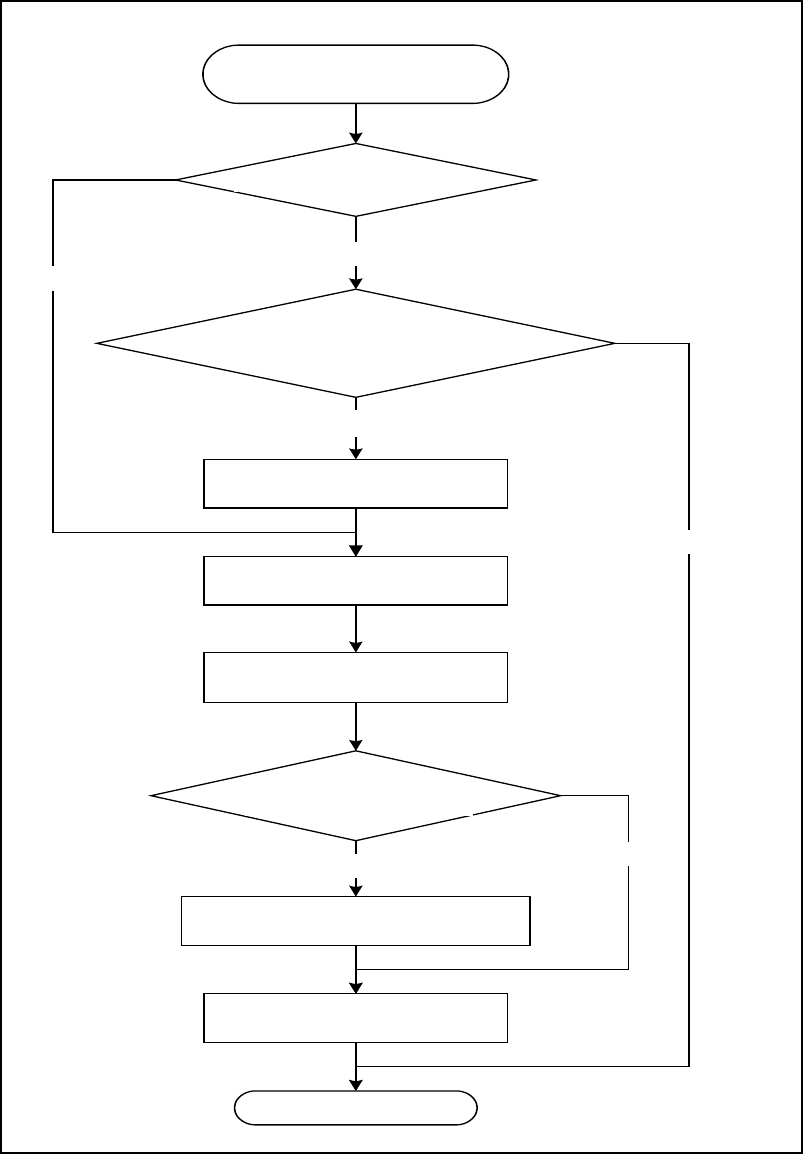
The following figure shows a conversion operation flow for using the CAD conversion
process:
入力フォーマットがあるか
CADデータの中身が
入力フォーマットを作成できる構成に
なっているか
入力フォーマットを作成する
はい
いいえ
ファイルの読み込み
データ変更ダイアログを
表示する設定である
データ変更ダイアログを表示する
はい
ない
いいえ
CADデータファイル
(基板・搭載・部品データ)
ある
終了
変換モードを選択する
ファイルを出力する
Figure 2-2 Conversion operation flowchart of Flexline CAD
End
Output a file
Display the data change dialog box
Yes
No
Read file
Select a conversion mode
No
Create an input format
Is an input format available?
CAD data file
(PWB, placement, and component data)
Are the contents of CAD data
configured to create an input format?
Is the setting intended to
display the data change
dialog box?
No
Yes
Yes
7
Chapter 3 Install
3.1 Environment required to use Flexline CAD
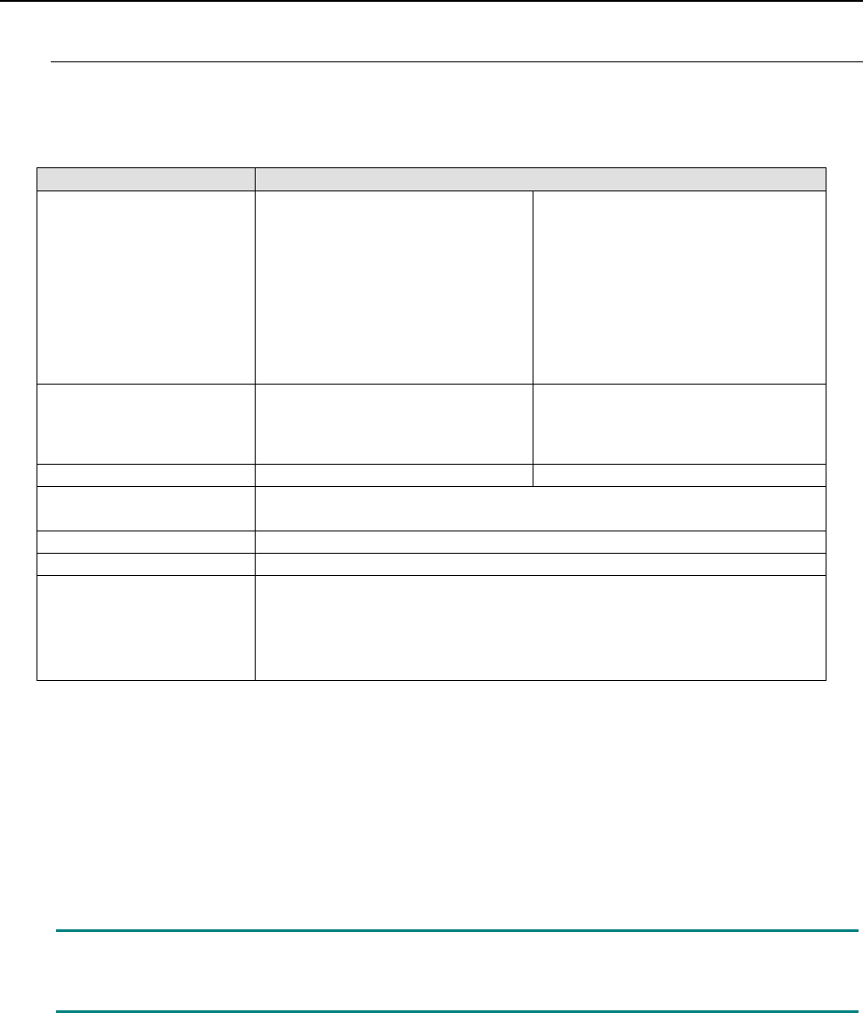
For using Flexline CAD, the following hardware devices and software are required.
Table 3.1-1 Operating environment
Recommended
Operating system
Microsoft Windows 95/98/NT *2
Microsoft Windows ME *5
Microsoft Windows 2000
Professional Service Pack 4 *5
Microsoft Windows XP Professional
Service Pack 2 or higher
Microsoft Windows Vista Business
Service Pack 1 or higher
Microsoft Windows 7 Professional
(32-bit version) *1
Microsoft Windows 7 Professional
(64-bit version)
Microsoft Windows 10 Pro (32-bit
version) *4
Microsoft Windows 10 Pro (64-bit
version) *4
Processor
Intel Pentium processor 3.2 GHz or
higher *1
(Intel Pentium Processor 1.3 GHz or
higher *2)
Intel Core2 Duo 2.40 GHz or higher
RAM
(256 MB or more *2)1 GB or more*1
(4 GB or more *3) 2 GB or more
Available hard-disk space
1 GB or more *1
(200 MB or more *2)
CD drive
Required
Display
Resolution of 1024 x 768 or more
Interface
Mouse
Keyboard
D-sub 25pin parallel port (conforming to Centronics) (*When using a parallel
type protect module)
USB 1/1/2.0/3.0 (*When using a USB type protect module)
* Intel, Pentium and Core2 Duo are trademarks of Intel Corporation in the U.S.A. and other countries.
* Microsoft, Windows 7, Windows Vista, Windows XP, Windows 2000, Windows ME, Windows NT, Windows 98 and
Windows 95 are trademarks of Microsoft Corporation in the U.S.A. and other countries.
*1 Enabled with the Version 6.00 or later only. (Some functions may be enabled with the latest version only.)
*2 Enabled with the Version 5.10 or earlier.
*3 When Microsoft Windows 7 Professional (64-bit version) or Microsoft Windows 10 Pro (64-bit version) is used
*4 Enabled with the Version 16.00 or later only. (Some functions may be enabled with the latest version only.)
*5 Enabled with the Version 15.00 or
earlier.
Note: If multiple applications are simultaneously started when using Flexline CAD,
operations may not be performed normally. Close applications other than Flexline CAD
in advance.