FLEXLINE-CAD_INM.pdf - 第105页
A-8 5.3 Fi eld transf ormatio n screen In this example, there is no item requiring transformation. Figure A - 1 1 PWB filed transformat ion screen Cl ick the "Next" butt on without performing any other operat…
A-7
5.2.2 Defining the field
Check whether the field position is correctly set. If it is wrong, select the line of the wrong field
and click the "Delete Field" button to delete the field. After deletion, set the correct field position
again.
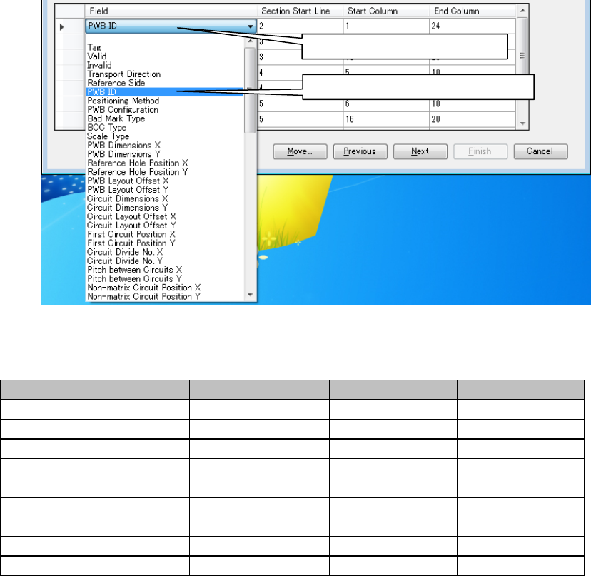
◊ Define the PWB ID field.
Figure A-10 PWB data field
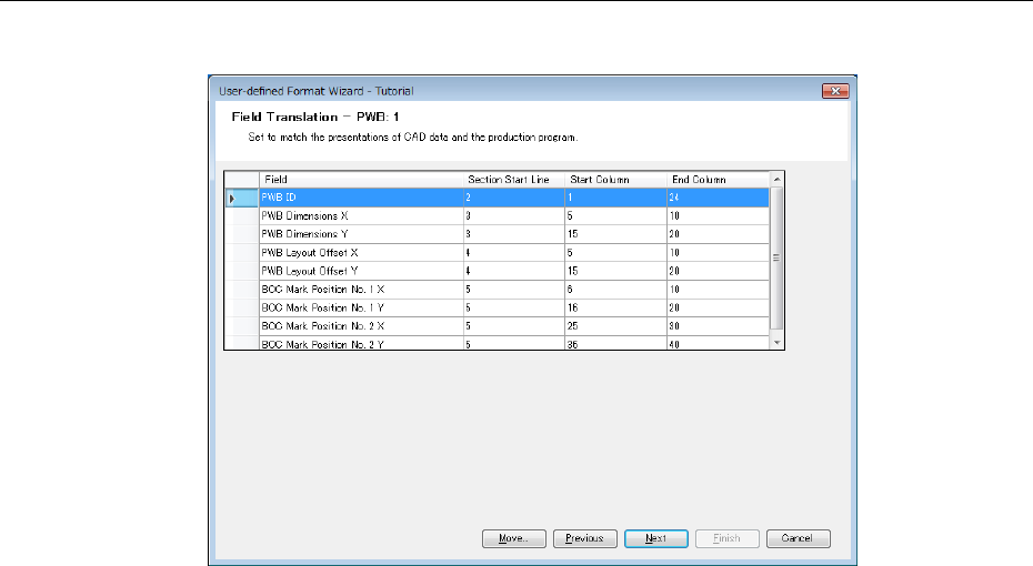
Likewise, set each field as shown below:
Field name
Section start line
Start column
End column
PWB ID
2
1
24
PWB outer dimensions C
3
5
10
PWB outer dimensions Y
3
15
20
PWB layout offset X
4
5
10
PWB layout offset Y
4
15
20
BOC mark position No.1 X
5
6
10
BOC mark position No.1 Y
5
16
20
BOC mark position No.2 X
5
25
30
BOC mark position No.2 Y
5
36
40
After completing the definition, click the "Next" button.
① Click here to display the list.
② Select the PWB ID from the list.
A-8
5.3 Field transformation screen
In this example, there is no item requiring transformation.
Figure A-11 PWB filed transformation screen
Click the "Next" button without performing any other operations.
* For the definition of multi-circuit non-matrix PWB, refer to the last part of Appendix A.
A-9
6. Placement Section
Next, the screen to define placement data is displayed.
6.1 Section definition screen
Move the scroll bar provided on the right side of "File display" downward by clicking it. Then, the
placement data screen is displayed.
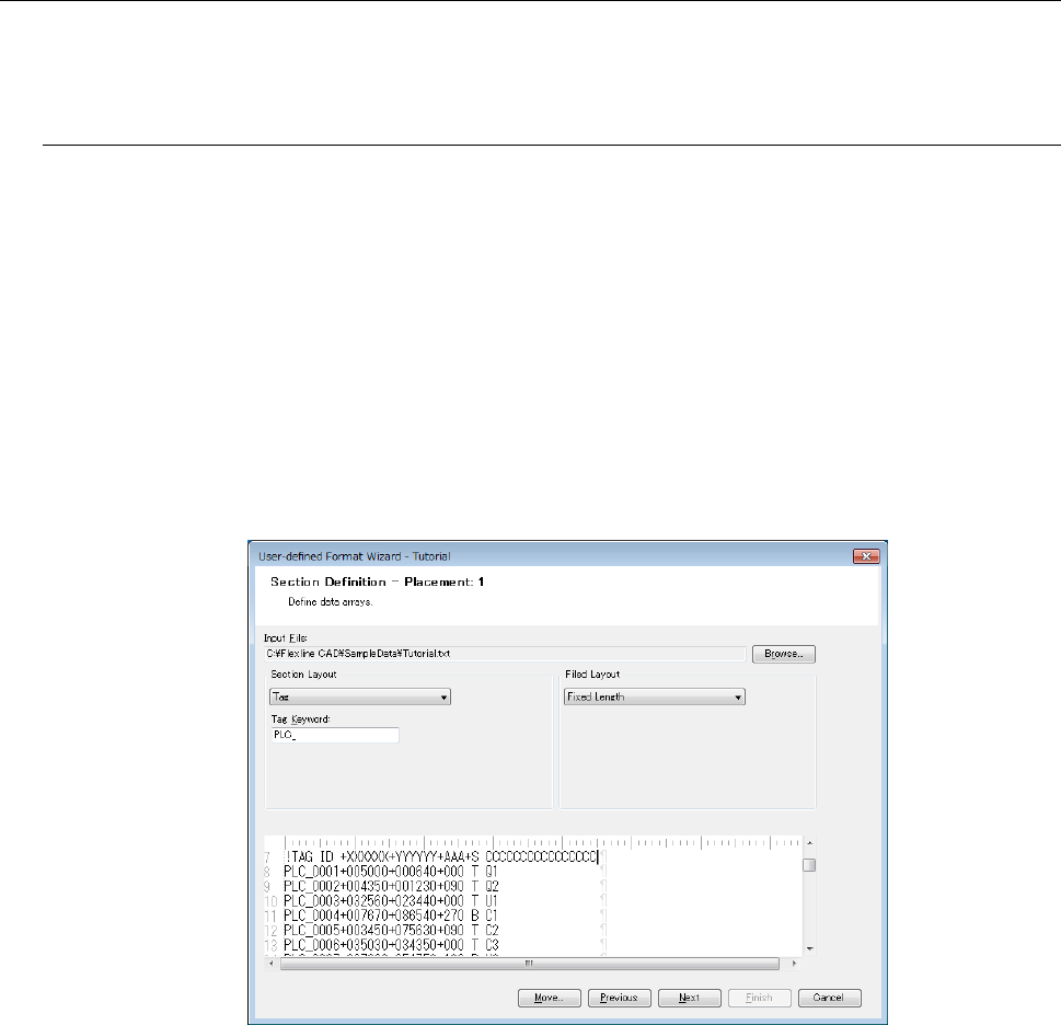
● Section layout
From the "Section Layout" list, select "Tag" and enter "PLC" in "Tag Keyword."
(Because the characters of "PLC" exist in the line of placement data)
● Field layout
From the "Field Layout" list, select "Fixed Length."
Figure A-12 Section Definition screen (placement)
Click the "Next" button.