FLEXLINE-CAD_INM.pdf - 第94页
89 10.3 Field The field names that can be used to define a field by the user - defined wizard ar e as shown below . The fields s hown in bold letter s require da ta conversi on setting on t he fiel d conversion screen of…
88
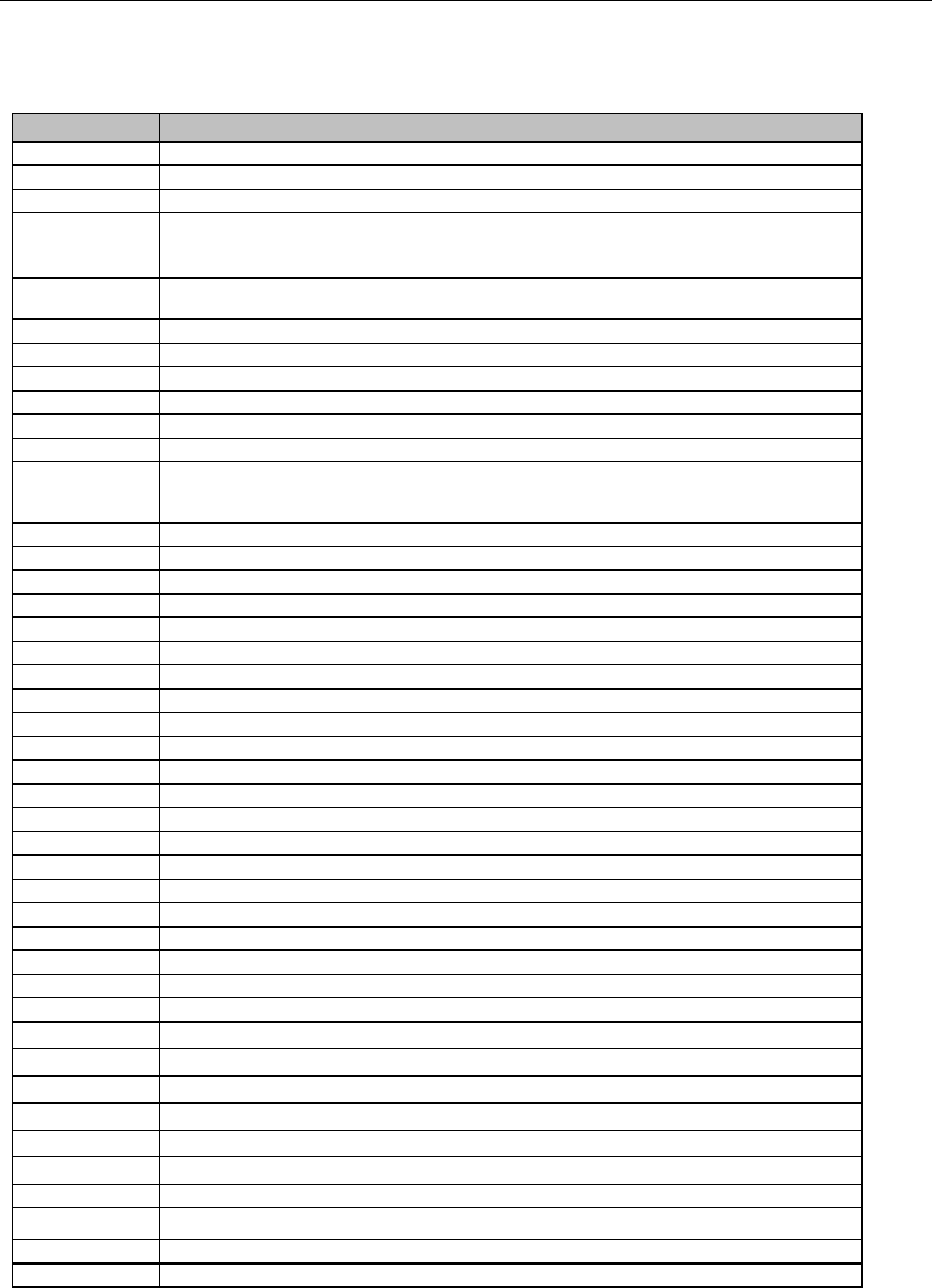
10.2 Data file extensions
The following table shows file types of the "Open" dialog box to be displayed at file selection
and the extensions of the user-defined wizard.
Table 10.2 Data file extensions
Extension
Explanation
*
All files
Bom
Extension used for the component list
Cad
Extension used for CAD, etc.
Csv
Data format for spreadsheet and data exchange between database software.
Its contents are a text file and each data (content of cell) is enclosed by " " and separated by
line feed. High versatility, being supported by lots of software.
Dat
Data file. This file is created by each application as required. Since this is a format peculiar to
the application, the source application must be found out.
Ini
System setup file used for Windows. Its contents are basically a text file format.
Iff
Interchange File Format type attached to the file used by COMODOR "AMIGA"
Log
Extension representing the Microsoft Help Workshop
Ncd
Extension used for some CAD files
Neu
Extension used for some CAD files
Pcb
Extension used for PWB data, etc.
Txt
Text file format. The most standard file format. Basically, editing can be performed by the note
pad. The file size that can be handled by the note pad is limited. Accordingly, for a large file,
the word pad is used.
g3h
File created by HLC Ver 4.0 to 4.4X
g4h
File created by HLC Ver 4.5
h4h
File created by HLC Ver 5.0 to 6.0
h5h
File created by HLC Ver 7.0 to 7.5
h6h
File created by HLC Ver 8.0 to 8.3
h7h
File created by HLC Ver 9.0
h8h
File created by HLC Ver 11.0
~
12.0
iss
File created by IS or IS Lite, JaNets
mlc
File created by LC-01
g3c
File created by KE730/KE750
g3g
File created by KE740/760
e41
File created by KE2010
e42
File created by KE2020
e43
File created by KE2030
e44
File created by KE2040
e45
File created by KE2050/KE2050R
e46
File created by KE2060/2060R/KE2055R
e47
File created by KE2070
e48
File created by KE2080./KE2080R
e51
File created by FX-1/FX-1R
e56
File created by CX-1
x01 File created by FX-3/FX-3R/ FX-3RA
x11 File created by KE3010/KE3010A *1
x21 File created by KE3020/KE3020R/KE3020V/KE3020VR/KE3020VA/KE3020VRA *1
j01x File created by RX-6/RX-6R *1
S01x File created by RS-1
x52
File created by FX-2 *1
g3d
File created by KD775
x4d File created by KD2077 *1
j11
File created by KJ01
j12
File created by KJ02
*1 Enabled with the Version 6.00 or later only. (Some functions may be enabled with the latest
version only.)
89
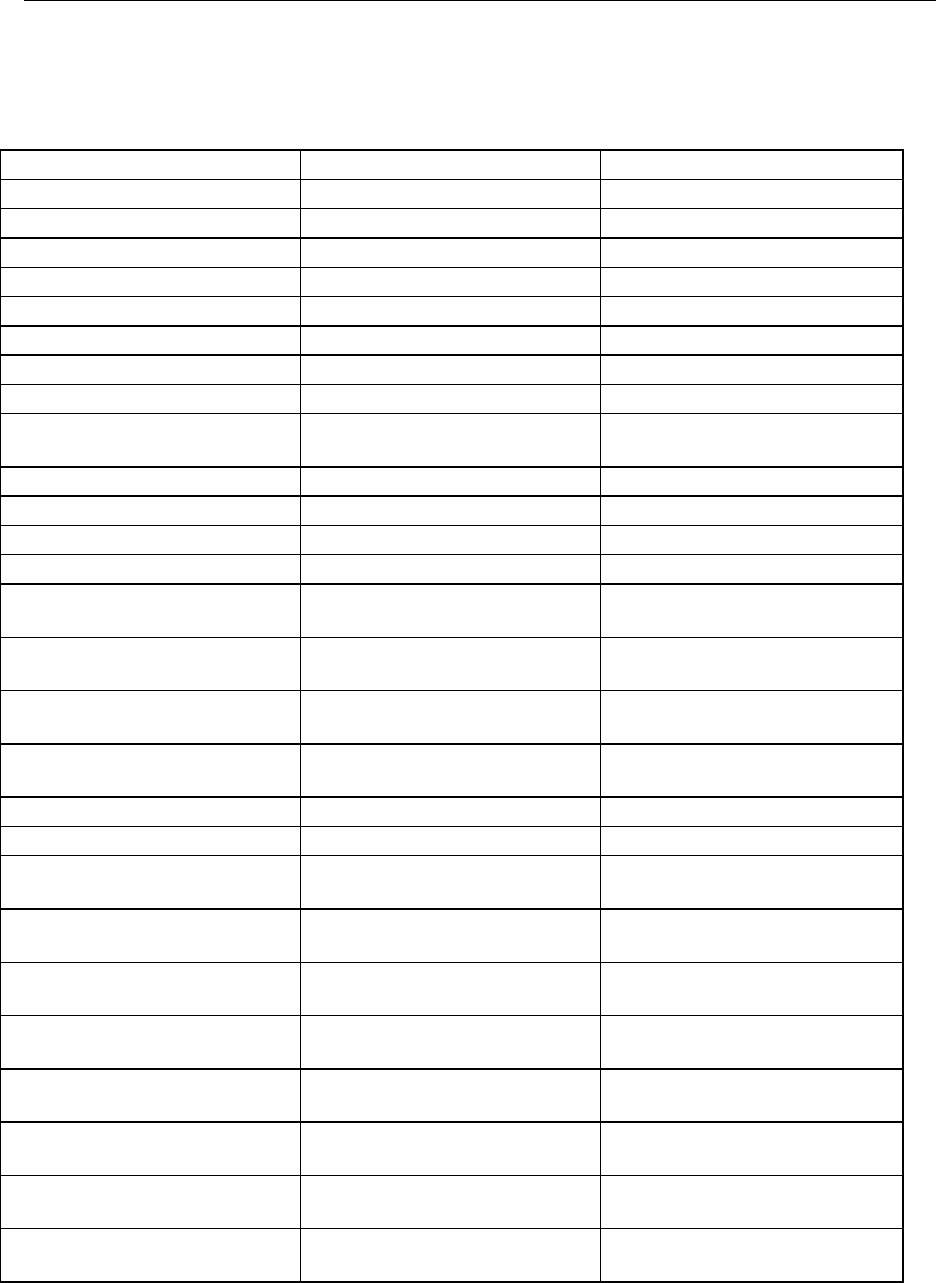
10.3 Field
The field names that can be used to define a field by the user-defined wizard are as shown
below. The fields shown in bold letters require data conversion setting on the field
conversion screen of the user-defined wizard.
Table 10-3 PWB fields
Tag
Valid
Invalid
Transport direction
Reference side
PWB ID *
Positioning method
PWB configuration
Bad mark type
BOC type
Mark recognition
PWB outer dimensions X
PWB outer dimensions Y
Positioning hole position X
Positioning hole position Y
PWB layout offset X
PWB layout offset Y
Circuit outer dimensions X
Circuit outer dimensions Y
Circuit layout offset X
Circuit layout offset Y
First circuit position X
First circuit position Y
Number of circuit divisions X
Number of circuit divisions Y
Pitch between circuits X
Pitch between circuits Y
Multi-circuit non-matrix circuit
layout position X
Multi-circuit non-matrix circuit
layout position Y
Multi-circuit non-
matrix circuit layout
angle
BOC mark position No.1 X
BOC mark position No.1 Y
BOC mark No.1 dimensions
BOC mark No.1 Name
BOC mark position No.2 X
BOC mark position No.2 Y
BOC mark No.2 dimensions
BOC mark No.2 Name
BOC mark position No.3 X
BOC mark position No.3 Y
BOC mark No.3 dimensions
BOC mark No.3 Name
BOC mark position (Bottom side)
No.1 X *1
BOC mark position (Bottom side)
No.1 Y *1
BOC mark (Bottom side) No.1
dimensions *1
BOC mark (Bottom side) No.1
Name *1
BOC mark position (Bottom side)
No.2 X *1
BOC mark position (Bottom side)
No.2 Y *1
BOC mark (Bottom side) No.2
dimensions *1
BOC mark (Bottom side) No.2
Name *1
BOC mark position (Bottom side)
No.3 X *1
BOC mark position (Bottom side)
No.3 Y *1
BOC mark (Bottom side) No.3
dimensions *1
BOC mark (Bottom side) No.3
Name *1
Bad mark position X
Bad mark position Y
PWB height
PWB thickness
The second BOC mark position
No.1 X *2
The second BOC mark position
No.1 Y *2
The second BOC mark No.1
dimensions *2
The second BOC mark No.1 Name
*2
The second BOC mark position
No.2 X *2
The second BOC mark position
No.2 Y *2
The second BOC mark No.2
dimensions *2
The second BOC mark No.2 Name
*2
The second BOC mark position
No.3 X *2
The second BOC mark position
No.3 Y *2
The second BOC mark No.3
dimensions *2
The second BOC mark No.3 Name
*2
The second BOC mark position
(Bottom side) No.1 X *2
The second BOC mark position
(Bottom side) No.1 Y *2
The second BOC mark (Bottom
side) No.1 dimensions *2
The second BOC mark (Bottom
side) No.1 Name *2
The second BOC mark position
(Bottom side) No.2 X *2
The second BOC mark position
(Bottom side) No.2 Y *2
The second BOC mark (Bottom
side) No.2 dimensions *2
The second BOC mark (Bottom
side) No.2 Name *2
The second BOC mark position
(Bottom side) No.3 X *2
The second BOC mark position
(Bottom side) No.3 Y *2
The second BOC mark (Bottom
side) No.3 dimensions *2
The second BOC mark (Bottom
side) No.3 Name *2
*1 Enabled with the Version 6.00 or later only. (Some functions may be enabled with the latest version
only.)
90
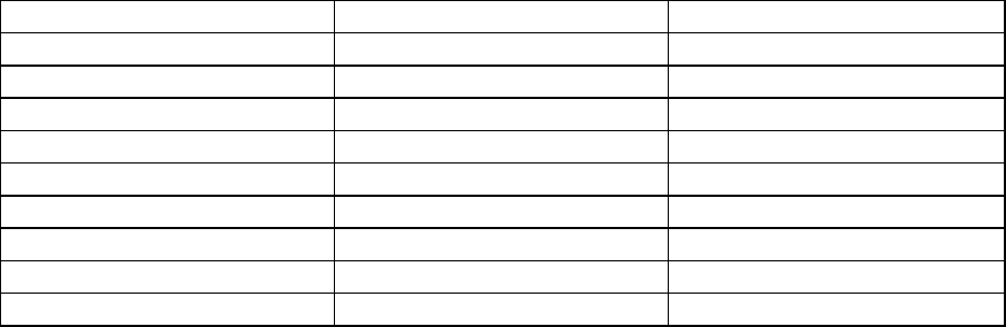
Table 10-4 Placement fields
Tag
Valid
Invalid
Placement side
Placement ID*
Link ID (BOM)
Placement position X
Placement position Y
Placement angle
Component name *
Placement/dispensing
IC mark type
IC mark ID
IC mark link
IC mark 1 X
IC mark 1 Y
IC mark 2 X
IC mark 2 Y
IC mark 3 X
IC mark 3 Y
Skip
Test run
Layer
Placement machine
Placement head
Dispensing skip
Dispensing test run
Dispensing machine
Dispensing head