FLEXLINE-CAD_INM.pdf - 第124页
C-4 ♦ "M K1C" and "M V1" Now , there is no difference in content s between MK1 and MV1. ● Data f iled names that can be transl ated PCB data Placement dat a Component dat a Not translated Placement ID…
C-3
♦
MENTOR
This format is mainly used in the U.S.A.
●
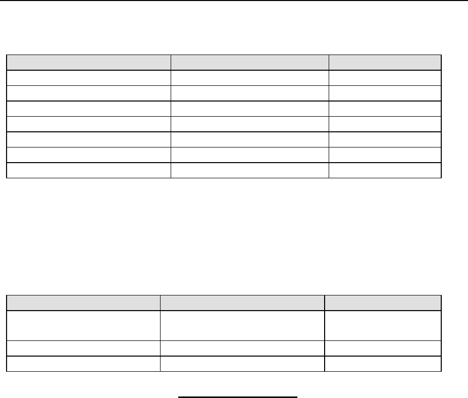
Data field names that can be translated
PCB data
Placement data
Component data
PCB ID *
1
Placement ID
Reference Designator
PCB Type *
2
Placement position X
Component Name
PCB layout offset X *
1
Placement position Y Component Comment
PCB layout offset Y *
1
Placement angle
Non-Matrix Circuit Position X *
3
Placement side *
4
Non-Matrix Circuit Position Y *
3
Non-Matrix Circuit Position Angle *
3
*
1
These fields are translated for “Single Board.”
*
2
PCB type is converted for “Single Board” and “Non-Matrix Board” only.
*
3
These fields are translated for “Non-Matrix Board.”
*
4
Placement Side is regarded as “Top” when the string is “1” and “Bottom when the
string is “2.”
●
Format definition
Data section
Section layout
Tag name
PCB data Tag format BOARD -> single board
P_ADDP -> Non-Matrix
Placement data
Tag format
COMP
Component data
Tag format
COMP
A sample of "MENTOR"
BOARD board2 OFFSET x:0.0 y:0.0 ORIENTATION 0
B_UNITS Mm.
Attribute Information
B_ATTR 'MILLING_ORIGIN' 'MILLING 0 0.0 0' 0.0 0.0
B_ATTR 'DRILL_ORIGIN' '' 0.0 0.0
B_ATTR 'BOARD_ROUTING_OUTLINE' '' -106.68 -2.54 -2.54 -2.54 -2.54 -73.66 38.1 -73.66 -
Component Information
COMP 1000 242202513341 conma1-3 con-52044-0310 20.25 24.5 1 180
C_PROP (MODEL,"mgc_models") (REFLOC,"MM,0.0,5.0,0,CC,1.2,1.2,0.2,leroy,1")
C_PIN 1000-1 20.25 24.5 0 1 180 2p00014 /N$2043
C_PIN 1000-2 19.0 22.0 0 1 180 2p00014-180 GND
C_PIN 1000-3 17.75 24.5 0 1 180 2p00014 /N$1840
COMP C1 222258016623 capstnd cap-0805 9.125 10.75 2 90
C_PROP (MODEL,"mgc_models") (FUNC_INC,"FN2")
C_PIN C1-1 9.125 9.5 2 2 90 2s00001 /N$1630
C_PIN C1-2 9.125 12.0 2 2 90 2s00001 /N$1389
COMP C10 202055292199 capstnd cap-0805 11.125 -62.375 2 90
C_PROP (MODEL,"mgc_models") (FUNC_INC,"FN1")
C_PIN C10-1 11.125 -63.625 2 2 90 2s00001 /N$1173
C_PIN C10-2 11.125 -61.125 2 2 90 2s00001 /N$1386
COMP C11 202055294073 capstnd cap-0805 5.375 -58.25 2 90
C_PROP (MODEL,"mgc_models") (FUNC_INC,"FN1")
C_PIN C11-1 5.375 -59.5 2 2 90 2s00001 /N$1840
C_PIN C11-2 5.375 -57.0 2 2 90 2s00001 /N$1174
C-4
♦
"MK1C" and "MV1"
Now, there is no difference in contents between MK1 and MV1.
●
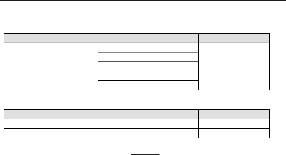
Data filed names that can be translated
PCB data
Placement data
Component data
Not translated
Placement ID
Not translated
Placement position X
Placement position Y
Placement angle
Component name
●
Format definition
Data section
Section layout
Tag name
PCB data
Placement data Tag format
GOMO
A sample
N0001/0G0M901T000X+002598Y+000500Z+00000V+00000W+00000 +00000D
N0002/0G0M901T000X-002180Y+000000Z+00000V+00000W+00000 +00000D
N0003/0G0M901T000X-004360Y+000000Z+00000V+00000W+00000 +00000D
N0004/0G0M901T000X-006540Y+000000Z+00000V+00000W+00000 +00000D
N0005/0G0M901T000X-006540Y-002850Z+00000V+00000W+00000 +00000D
N0006/0G0M901T000X-004360Y-002850Z+00000V+00000W+00000 +00000D
N0007/0G0M901T000X-002180Y-002850Z+00000V+00000W+00000 +00000D
N0008/0G0M901T000X+000000Y-002850Z+00000V+00000W+00000 +00000D
N0009/0G1M000T004X+000000Y+000000Z+00000V+00000W+00000 +00000D
N0010/0G0M004T000X+012034Y-021796Z+00001V+00090W+00090 +00000D
N0011/0G0M004T000X+012499Y-022541Z+00002V+00000W+00000 +00000D
N0012/0G0M004T000X+012214Y-021791Z+00002V+00090W+00090 +00000D
N0013/0G0M004T000X+012058Y-022155Z+00004V+00090W+00090 +00000D
N0014/0G0M004T000X+012814Y-022201Z+00005V+00090W+00090 +00000D
N0015/0G0M004T000X+012234Y-022151Z+00006V+00090W+00090 +00000D
N0016/0G0M004T000X+012234Y-022541Z+00007V+00090W+00090 +00000D
C-5
♦
"Panasonic"
There are two types of Placement data files as follows:
.NCD data file
.POS data file
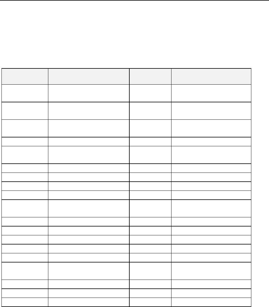
The following table describes the relationship among the Panasonic machine name, machine
number, file type and the input format names supported by Flexline CAD.
Table Pana-1 Panasonic Machines and Flexline CAD Input Formats
Machine
Name
Machine Number File Type
Input Format in Flexline
CAD
MPA 40 / 80 NM-2528
NM-2529
NCD MPA4080
MPA NM-2523
NM-2524
NCD
MPA
MK1C NM-2562C
NM-2565C
NCD
MK1C
MK2C
NM-2563C
NCD
MK2C
MK1 NM-2562
NM-2662B
NCD
MK1
MK2
NM-2563
NCD
MK2
MKH NM-2564 NCD MKH
MR NM-2560 NCD MR
MR 20 / 3
NM-2560
NCD
MR20
MQ1 NM-8256C
NM-8257C
NCD MQ1
MQ2
NM-8251C
NCD
MQ2
HD
NM-2621
NCD
HD
HD3
NM-2626C
NCD
HD3
MVI NCD MV1
MVIIA-B
NCD
MV2AB
MVII-C,F NM-2558
NM-2559
POS MV2C
MV2F
MPAIII
POS
MPA3
MSH1
POS
MSH1
MPA-V
POS
MPAV
The Panasonic data type uses two methods. XY coordinates can be entered with the absolute
method or the incremental method. Flexline CAD only supports ABS method.
Absolute method (ABS): Coordinate origin is always the basis for the placement position of
each component.
Incremental (INC): Placement position of each component is not determined from the
coordinates’ origin. Instead, it is determined to be the travel distance from the placement
position of the previous component. Therefore, X and Y coordinates represent the distance
from the center of one component’s placement position to the center of the next
component’s placement position.