FLEXLINE-CAD_INM.pdf - 第31页
26 (2) Edit menu Figur e 4.3.1 - 3 "Edit" menu (3 ) Convert me nu Figur e 4.3.1 - 4 "Convert" m enu (4) Format menu Figur e 4.3.1 - 5 "Format" menu (5) T ool menu Figur e 4.3.1 - 6 "T o…
25
4.2 Exiting Flexline CAD *1
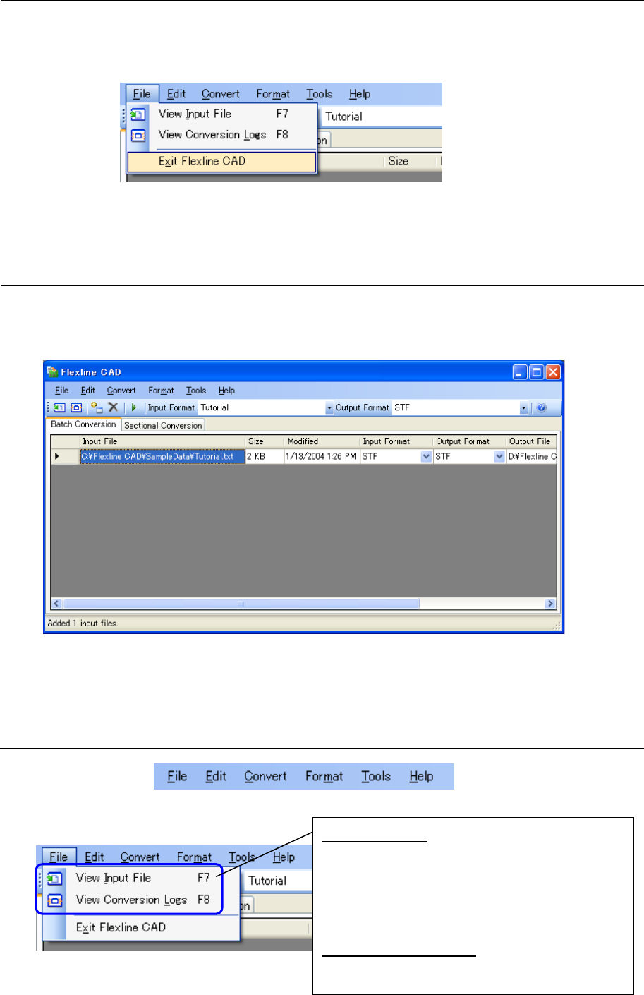
Select the "File" - "Exit Flexline CAD" on the main screen, or click the "x" button provided in the
upper right part of the title bar. After that, when the exit confirmation message is displayed, click
the [Yes] button.
Figure 4.2-1 "Exit Flexline CAD" menu
*1. The screen displayed with the Version 5.10 or earlier is different from that with the Version
6.00 or later.
4.3 Screen configuration of Flexline CAD *1
This section describes operations on the screen.
After Flexline CAD is booted up, the main screen is displayed to enable operations for
conversion.
Figure 4.3-1 Main screen of Flexline CAD (batch conversion mode)
*1. The screen displayed with the Version 5.10 or earlier is different from that with the Version
6.00 or later.
4.3.1 Menu bar of Flexline CAD
Figure 4.3.1-1 Menu bar of Flexline CAD
(1) File Menu
Figure 4.3.1-2 "File" menu
View Input File:
The input file of the line selected in the file
table is displayed by the application related to
the file extension.
Displays the input of the line selected in the file
table with the application related to the file
extension.
View Conversion Logs:
Displays the conversion logs.
26
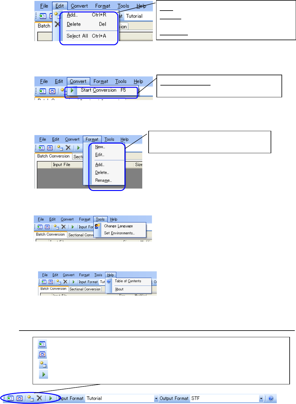
(2) Edit menu
Figure 4.3.1-3 "Edit" menu
(3) Convert menu
Figure 4.3.1-4 "Convert" menu
(4) Format menu
Figure 4.3.1-5 "Format" menu
(5) Tool menu
Figure 4.3.1-6 "Tool" menu
(6) Help menu
Figure 4.3.1-7 "Help" menu
4.3.2 Flexline CAD's Tool Bar
Figure 4.3.2-1 Tool bar of Flexline CAD
(View input file): Displays the input file by the application related to the file extension.
(View conversion log): Displays the conversion log by the application related to the file extension.
(Add input file): Adds the input file to the file table.
(Start conversion): Starts conversion for the selected file table.
Add: Adds the input file to the file table.
Delete: Deletes the input file on the line selected
in the file table from the file table.
Select All: Selects all the line of the table.
Start Conversion: Starts conversion for the
selected file table.
Creates an input format newly, and edits,
adds, and deletes an input format.
27
Chapter 5 Batch Conversion and Sectional Conversion *1
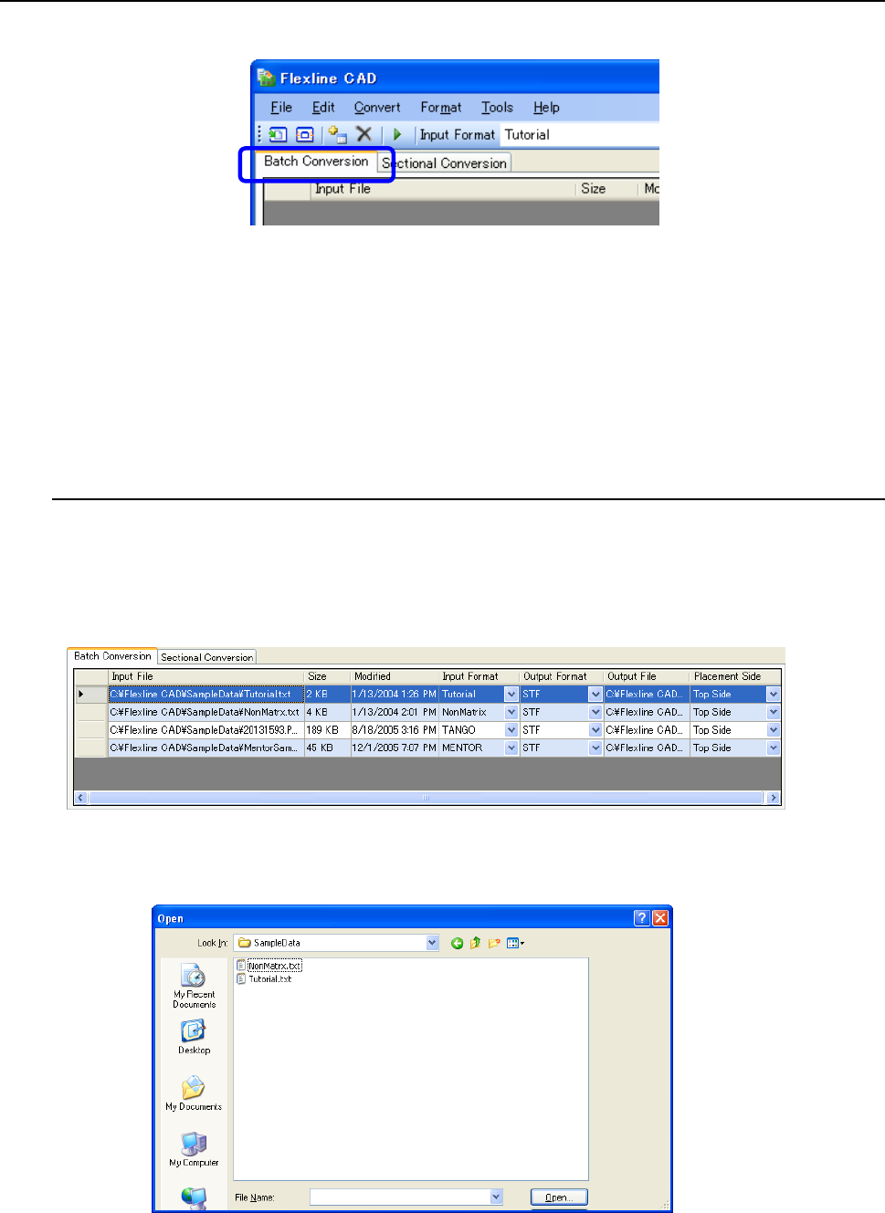
The conversion mode can be selected by selecting the "Batch conversion" tab or "Sectional
conversion" tab of the main screen.
Figure 5-1 Selection of conversion mode
The column width of the file table can be freely adjusted. Put the mouse cursor to the boundary
on the right side of each column header. When the cursor shape is changed into left and right
two lines of the arrow, drag the boundary. Thus, the column width can be narrowed or
extended.
*1 The screen displayed with the Version 5.10 or earlier is different from that with the Version
6.00 or later.
5.1 Batch conversion mode
Select the "Batch conversion" tab on the main screen. At this time, one or multiple CAD data
can be converted simultaneously. For example, if four input files are added to the batch
conversion file table and conversion is started, all the input files are converted sequentially from
the top. During conversion, the selected line of the conversion file table is shifted to indicate the
file being processed.
Figure 5.1-1 Batch conversion file table
Regarding "Input file" or "Output file", double-click the cell or select the cell and then press the
"Enter" key. Then, the following dialog box is displayed to change the file.
Figure 5.1-2 "Open file" dialog box