YST15_Users_E.pdf - 第20页
1-4 1 Unit names and functions 1.1 Operation buttons 4 3 2 5 1 Operation buttons 23103-KMS-00 1. Main switch T his switc h turn the machine power supply on/off. T urn “0” to “1” to turn on the machine. 2. Operation switc…
1-3
1
Unit names and functions
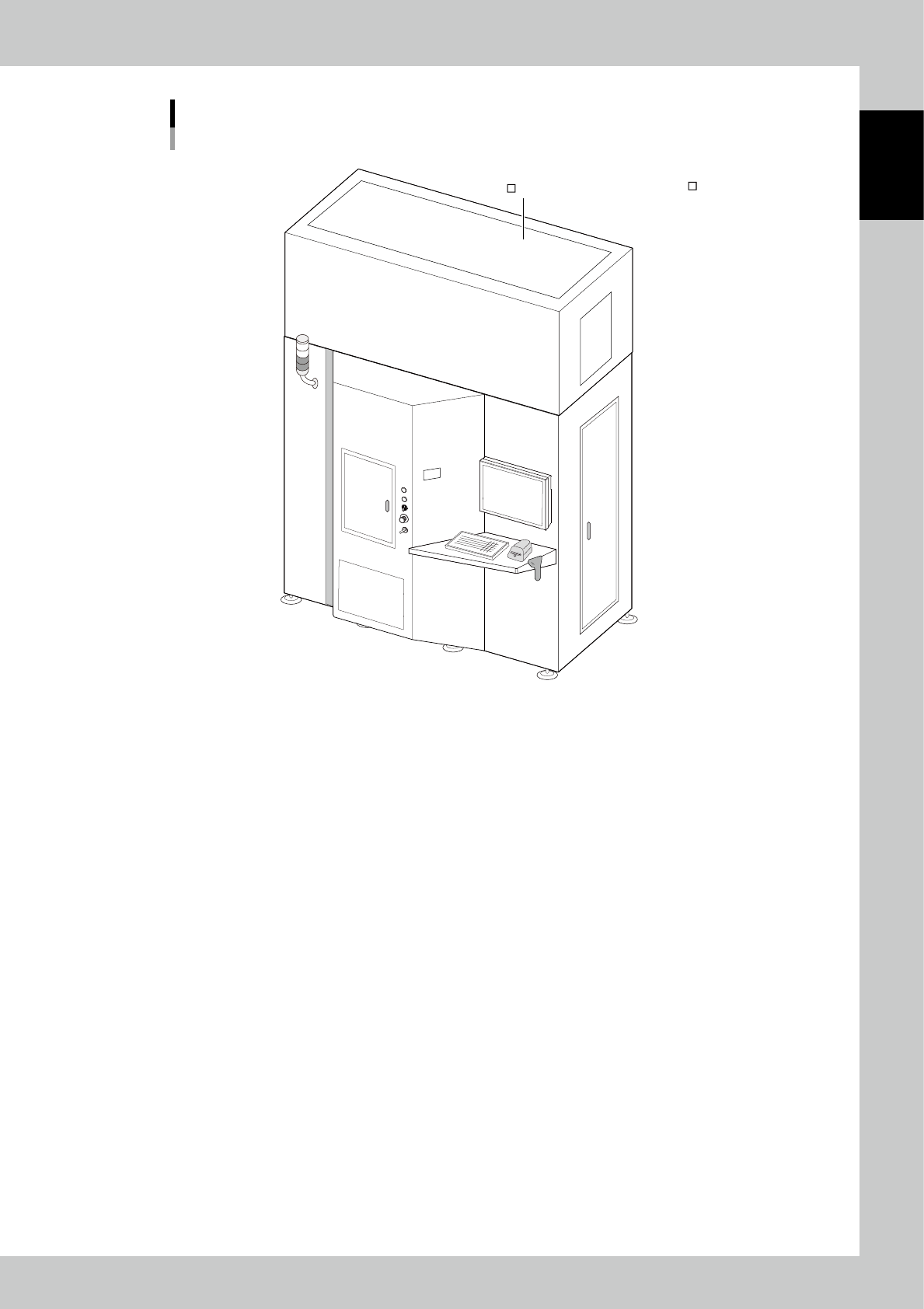
Machine main unit
Extension specification
Front
n : Standard units
: Options
Extension unit
23102-KMS-00
1-4
1
Unit names and functions
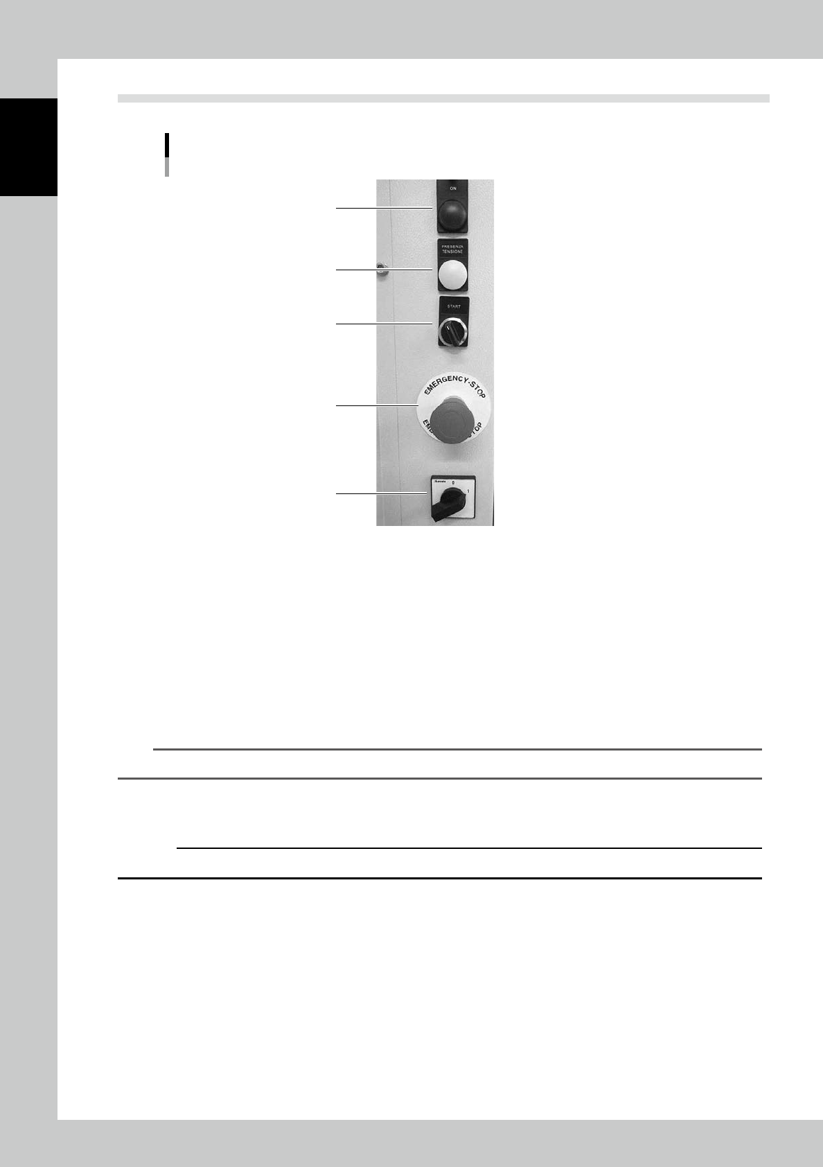
1.1 Operation buttons
4
3
2
5
1
Operation buttons
23103-KMS-00
1. Main switch
This switch turn the machine power supply on/off. Turn “0” to “1” to turn on the machine.
2. Operation switch
This button starts the machine operation. Turning it right turns on the control board, axes boards, motors, sensors,
dehumidifiers, and so on.
3. Power indicator (Green: Boot OK)
This lamp lights on when the operation switch is on.
4. Operation indicator
This lamp lights on when the operation is ready after all the boards are on by turning the operation switch.
TIP
The boards are powered on approximately 5 seconds after turning the switch on.
5. Emergency stop button
This button turns off the power supply for controlling all axes. Turn the button left to cancel the emergency stop.
c
CAUTION
Do not use emergency stop button except for emergency.
1-5
1
Unit names and functions
1.2 Operator area
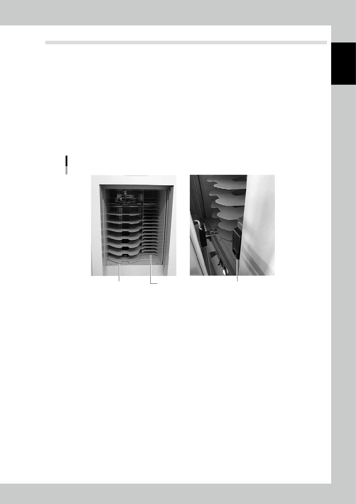
Operators use the touch screen, the keyboard, and the mouse to load/unload components.
Operator area
• Front door
• Safety door lock
The door is used for loading/unloading components.
The door is locked and can’t be opened during the axis operation for loading/unloading.
While the door opens, it is not possible to operate loading/unloading, initialization, and so on which are associated with
the axis operation.
• Loading/unloading area
The shelf is used to load/unload components.The right side is for 7 inches reels and the left side is for 13-15 inches reels.
* Depending on the machine type.
Loading/unloading area
Door lockFor 7 inch reelsFor 13-15 inch reels
23104-KMS-00