00198829-01_SM_X-Series-S_Hxxxx_EN.pdf - 第111页
6 Gantries 6.3 X and Y axis Service Manual SIPLACE X-Series S (from Hxxxx) 01/2021 111 6.3.4 Track Signals and Zero Pulse Equipment and tools Fig.139: Test devices PG1-I and PG-U Select the testing device suitable for y…
6 Gantries
6.3 X and Y axis
110 Service Manual SIPLACE X-Series S (from Hxxxx) 01/2021
Removal
► Switch off the machine, disconnect it from the power supply and secure it to prevent
unauthorized reactivation.
1.2 "Preparatory work..." [}16]
► Unplug the incremental encoder cable from the gantry interface. In this case make a note of
the position to make clear assignment easier later on.
► Unthread the connection cable as far as the incremental encoder.
► Remove the three screws fastening the bracket and then carefully remove this together with
the incremental encoder on it.
► Remove the two screws fastening the incremental encoder and then carefully remove this
from the bracket.
Installation
► Clean the reading surface of the incremental encoder with a cloth and ethanol or with a Q tip.
► Use the two screws to fasten the incremental encoder to the bracket.
► Use the three screws to install the bracket. To do this, place the thickness gauge provided
between the incremental encoder and the scale, so that there is a gap. This gap must either
be 0.4mm
(golden scale) or 0.75mm (black-white scale). Use the corresponding thickness
gauge.
► Reconnect to the electricity supply.
CAUTION
Make sure that the cables do not rub against anything.
Make sure that the axes can be moved without damaging the cables.
► Fasten them with cable ties
► Check the track signals with the test device (see 6.3.4 "Track Signals and Zero
Pulse" [}111]).
6.3.3 Mechanical adjustment of the incremental encoder
The incremental encoders (read units) on the X and Y axis are adjusted exactly to the position of
the incremental scale. The two limit marks on the incremental encoder show where the top/bottom
positions of the scale should be.
Set the incremental encoder mechanically to a distance of 0.75 mm to the incremental encoder.
NOTICE
Plastic disks
To set this distance, use one or more small plastic disks with a total thickness of 0.75mm.
► Feeler gauge 0.75mm plastic [03090774-xx]
After this adjustment of the incremental encoder you have to check the zero pulse and track sig-
nals.
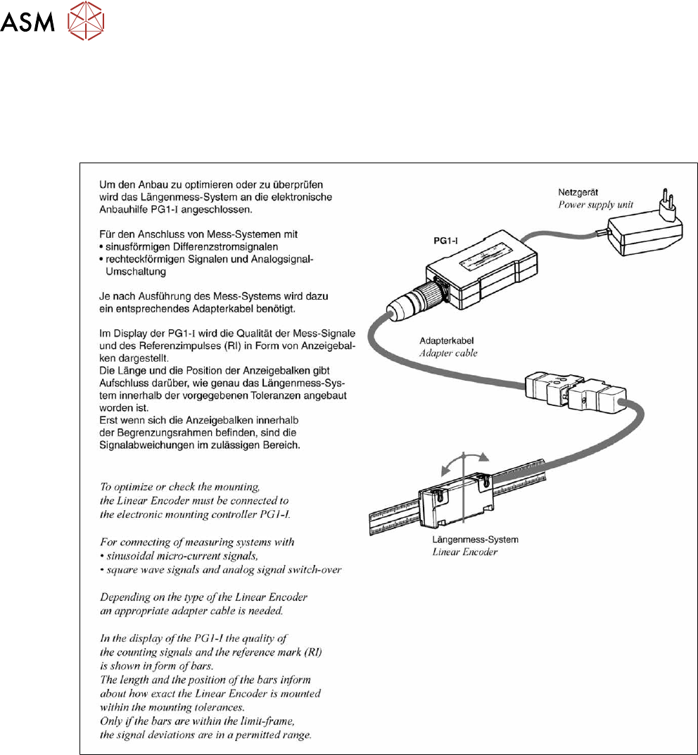
Correct installation should ensure correct count and zero pulse signals. For troubleshooting pur-
poses (error analysis and fixing), you will need to measures these signals.
Please also observe section 6.3.4 "Track Signals and Zero Pulse" [}111].
6 Gantries
6.3 X and Y axis
Service Manual SIPLACE X-Series S (from Hxxxx) 01/2021 111
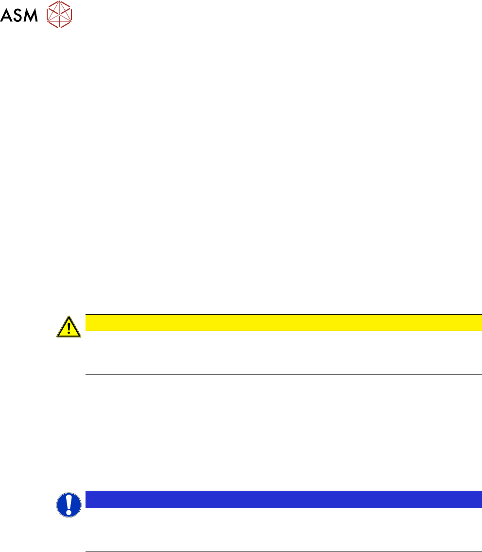
6.3.4 Track Signals and Zero Pulse
Equipment and tools
Fig.139: Test devices PG1-I and PG-U
Select the testing device suitable for your incremental encoder:
●
For MS22/25 incremental encoder: test device PG1-I [03102699‑xx]
●
For MS20/30/35 incremental encoder: test device PG-U [03071361‑xx]
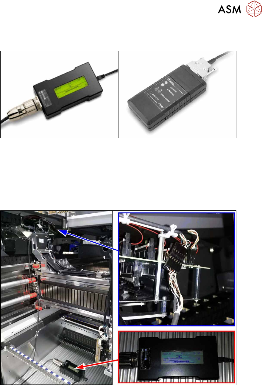
Checks
Proceed as follows to check the zero pulse:
► Switch off the machine.
Fig.140: Test device
► Unplug the incremental encoder from the head interface or the gantry interface and connect it
to the test device (see also 6.3.4.1
"Test device – operation" [}112]).
► Move the head or gantry manually back and forth. This movement enables you to read the
correct track signal progress from the test device.
► If the track signal is not within the tolerance range, you will need to reset the incremental en-
coder. The incremental encoder has then been fitted either too near, too far away, inclined
and/or displaced.