00198829-01_SM_X-Series-S_Hxxxx_EN.pdf - 第41页
2 Basic Machine 2.8 Nozzle Changers and Reject Boxes Service Manual SIPLACE X-Series S (from Hxxxx) 01/2021 41 Removal NOTICE Short and long nozzle changer The procedure for removal and installation is the same for the s…
2 Basic Machine
2.8 Nozzle Changers and Reject Boxes
40 Service Manual SIPLACE X-Series S (from Hxxxx) 01/2021
2.8.3 Replacing the Nozzle Changer
NOTICE
Row two, MTC2, WPC
For more information about the row 2 nozzle changers and in combination with MTC2/
WPC, refer to the assembly instructions "NC row 2 - NC before MTC 2/
WPC" [DEEN:00197369‑xx].
Parts, equipment and tools
Select the relevant nozzle changers:
●
NC basic structure CPx/all assembly long [03147324–xx] (replaces [03103514‑xx]
[03070123‑xx])
●
NC CPx/all short [03147925‑xx] (replaces [03103649-xx] [03062463-xx])
●
Magazine holder assembly / NC P+P B series [03062453‑xx]
●
If required, NC shim plates [03021079-xx]
●
Depth measuring gauge (300mm) [03079617-xx]
●
Plastic plate
Overview
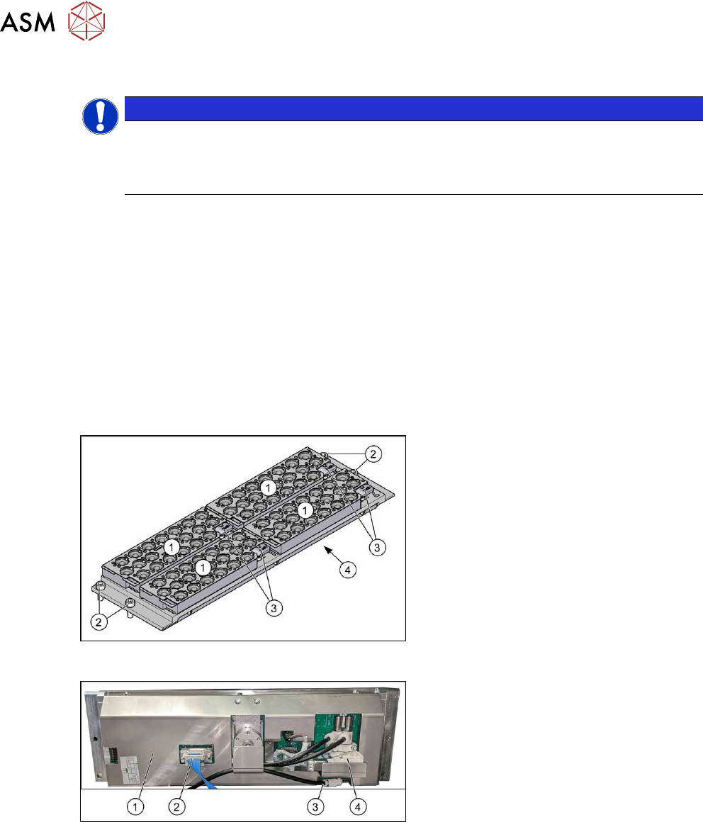
Fig.35: Nozzle changer with four nozzle magazines
1. Four nozzle magazines (4xxx/6xxx)
2. Four fixing screws
3. Four levers for removal of nozzle
magazines
4. Cover on the underside
The electronic and pneumatic compon-
ents are under the cover.
Fig.36: Overview of nozzle changers
1. Cover
2. Electrical connection
3. Compressed air connection
4. Valve

2 Basic Machine
2.8 Nozzle Changers and Reject Boxes
Service Manual SIPLACE X-Series S (from Hxxxx) 01/2021 41
Removal
NOTICE
Short and long nozzle changer
The procedure for removal and installation is the same for the short and long nozzle
changer.
► Switch off the machine, disconnect it from the power supply and secure it to prevent
unauthorized reactivation.
1.2 "Preparatory work..." [}16]
► Switch off the compressed air supply
5.2 "Disabling the compressed air supply" [}86]
► Remove all magazines.
► Remove the four fastening screws.
► Unplug the nozzles changer from all electrical and pneumatic connections. You might like to
mark their positions to make clear assignment easier later on.
► Take care not to lose the support plates. Remember their exact positions, as they will need to
be returned to these original positions, during assembly.
► Carefully lift the nozzle changer out of the machine.
Installation
Follow the removal instructions in reverse order for installation. Also observe the following instruc-
tions:
► If present: check the jumper on the nozzle changer.
2.8.6 "Jumpers on the Nozzle Changer" [}44]
► Re-insert the support plates.
► Check the mechanical installation height of the nozzle changer.
2.8.5 "Setting the Nozzle Changer Height" [}43]
2 Basic Machine
2.8 Nozzle Changers and Reject Boxes
42 Service Manual SIPLACE X-Series S (from Hxxxx) 01/2021
2.8.4 Setting the Nozzle Reject and Station Height
Parts, equipment and tools
●
Depth measuring gauge (300mm) [03079617-xx]
●
Shim plates for nozzle reject device [03039514-xx]
●
Screws DIN 7991-M4 x 20-8.8 [00333782-xx]
●
Plastic sheet (to keep the depth measuring gauge away from the magnets)
Setting
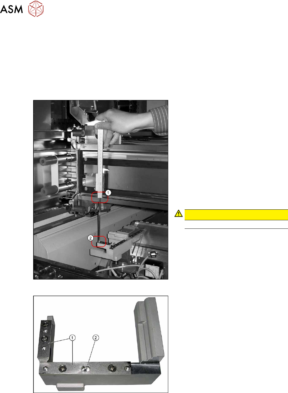
Fig.37: Measurement
1. Position upper edge of measuring scale
on the linear guidance
2. Bottom end of measuring gauge on the
assembly surface of the nozzle station
► Push the placement head to be meas-
ured outwards.
► Place a plastic plate in front of the mag-
nets.
► Position the measuring gauge on the
upper edge of the nozzle station
assembly surface and measure the dis-
tance to the upper edge of the lower X
axis linear guidance.
CAUTION!
Hold the measuring scale vertically!
.
Fig.38: Shim plates
1. Shim plates
2. Slot
► Set a distance of 139.0±0.2mm for all
placement heads.
If the distance is too large, insert shim
plates:
shim plates for nozzle stripping
device[03039514‑xx],
screws DIN7991 M4x20 - 8.8
[00333782‑xx]