00198829-01_SM_X-Series-S_Hxxxx_EN.pdf - 第87页
5 Pneumatic System 5.3 Setting the pressure for the machine components Service Manual SIPLACE X-Series S (from Hxxxx) 01/2021 87 Fi g . 1 0 1 : V e n t in g t he c u tt e r (e x a m pl e o f S I P LA C E SX 1 V 2 s h …
5 Pneumatic System
5.2 Disabling the compressed air supply
86 Service Manual SIPLACE X-Series S (from Hxxxx) 01/2021
5.2 Disabling the compressed air supply
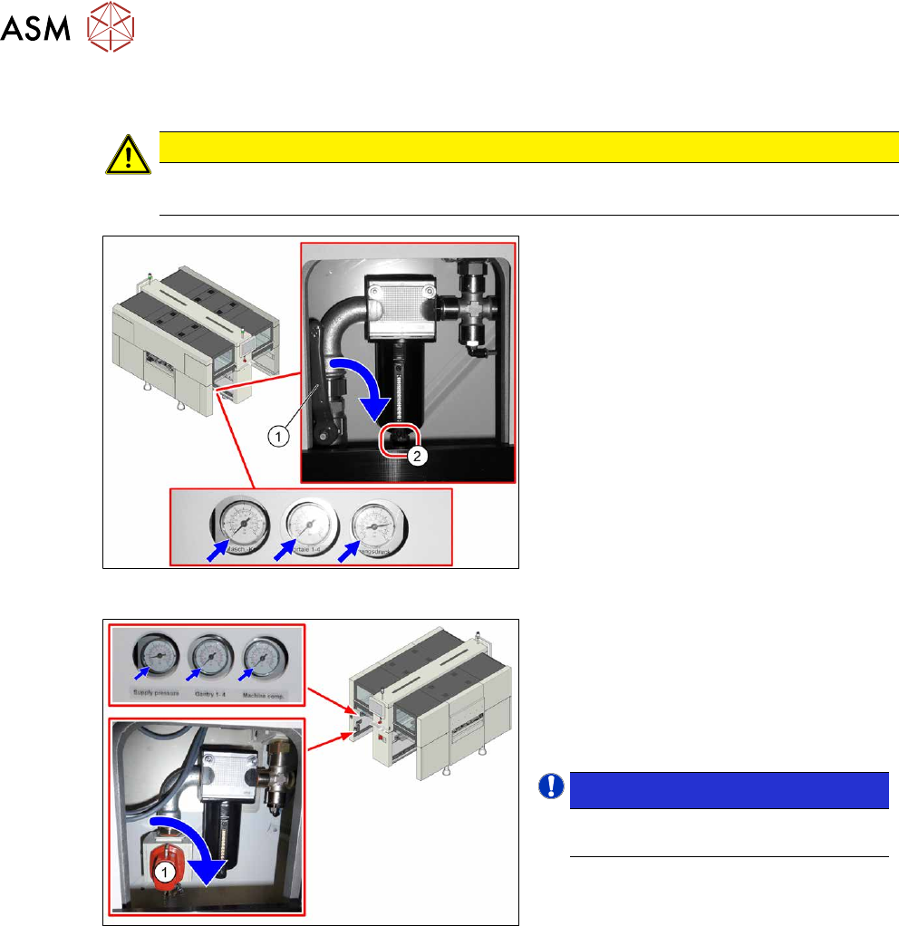
CAUTION
Switch off the compressed air supply
The compressed air supply must always be switched off for all work on the pneumatic system.
Fig.99: Disabling the compressed air supply (version 1)
Version 1:
► Push the lever (1) for the compressed
air supply down until it is positioned ho-
rizontally.
► Open the screw (2) on the inlet filter to
vent the system. Hold a cloth under-
neath to capture any escaping liquid.
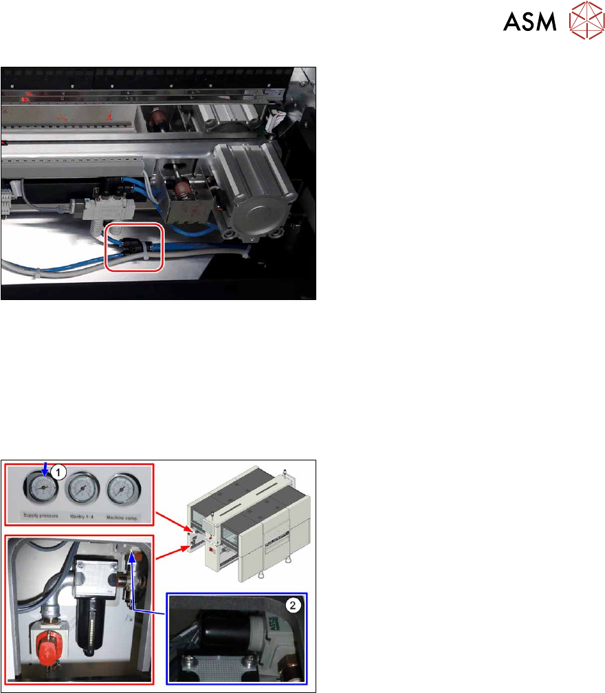
Fig.100: Shutting off the compressed air supply (version 2)
Version 2:
► Push the switch (1) for the compressed
air supply by 90 degrees, until it is posi-
tioned horizontally.
► All pressure gauges must be set to
zero.
NOTICE!
Venting is performed automatically
in this version.
.
If you are working on cutters, you will need to vent these as follows:
5 Pneumatic System
5.3 Setting the pressure for the machine components
Service Manual SIPLACE X-Series S (from Hxxxx) 01/2021 87
Fig.101: Venting the cutter (example of SIPLACE SX1V2 shown)
► Pull one of the thinner pneumatic hoses
of the T-section on the cutter.
See also
2 1.1.5 "Safety instructions for work on the cutting device" [}15]
2 1.1.4 "Safety instructions for the compressed air supply" [}15]
5.3 Setting the pressure for the machine components
Fig.102: Pressure for machine components
► Make sure that the pressure for
machine components is set to
5.1bar(1)
.
► Correct the pressure where necessary,
with the pressure control valve(2)
.
5 Pneumatic System
5.4 Sealing the Pneumatic Screwed Connections
88 Service Manual SIPLACE X-Series S (from Hxxxx) 01/2021
5.4 Sealing the Pneumatic Screwed Connections
NOTICE
Sealing the pneumatic screwed connections
If pneumatic screwed connections are loosened, these will need to be sealed again after-
wards. Always use the same sealing technique as was used before they were removed.
The following sealing techniques are available:
► Sealing ring (rubber or plastic)
These are either supplied or you can use the ones used before. Check the condition of
used sealing rings for damage.
► Sealant
There are several variants of this:
Loctite 567 [03097172-xx] and Loctite 55 [03092492-xx]
After loosening the pneumatic screwed connection, clean the screwed thread and seal
it with Loctite. The sealing thread for Loctite 55 must be wound on in the direction of
the screwed thread.
There may also already be a sealant on the screwed thread.
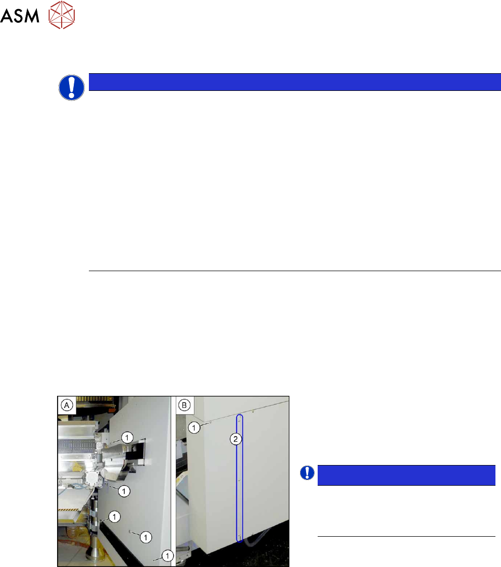
5.5 Dismantling the Lower Side Cover
Most tasks require that you dismantle the lower side cover (corner cover) from the location. This is
shown below using the example of location 2. The procedure is the same for other locations.
Parts, equipment and tools
●
Shortened Allen key, if required
Dismantling the side cover
Fig.103: Dismantling the lower side cover
► While unscrewing, always hold on to
the side cover, to prevent it falling off.
► Remove the six screws(1) fastening
the inner(A)
and outer side(B) of the
side panel.
NOTICE!
The three fastening screws (2) on the
outer side are loosened as a default.
The side cover can be pulled out here.
.
► Remove the side cover.
Fitting the side cover
► Assembly is performed by following the above instructions in the reverse order.