00198829-01_SM_X-Series-S_Hxxxx_EN.pdf - 第232页
7 Conveyor 7.8 Laser light barriers, fiber optic cable and PCB sensors 232 Service Manual SIPLACE X-Series S (from Hxxxx) 01/2021 NOTICE Fiber optic cable ruptured at the trailing chain If the fiber optic cable is ruptur…
7 Conveyor
7.8 Laser light barriers, fiber optic cable and PCB sensors
Service Manual SIPLACE X-Series S (from Hxxxx) 01/2021 231
Equipment and tools
03017821-xx Loctite 406 (instant glue highly viscous)
03019481-xx Dosage tip for Loctite
00372972-xx Protective latex gloves
00353832-xx Allen key set
Cable tie
Wire cutters
Troubleshooting
► In the station software, activate all fiber optic cables (transmitters). These may need to be re-
calibrated without boards in the conveyor.
► A red light must be visible for the transmitters.
If no light is visible at the transmitter, there is probably an error.
► As a cross-check, you can switch the transmitting and receiving fiber optic cable at the corres-
ponding fiber optic sensor (WLL180T-F preconfigured SXa [03093295‑xx] or WLL180T-M pre-
configured SXa [03093294‑xx]).
NOTICE
Do not confuse the transmitter with the receiver
► Make sure not to confuse the transmitting and receiving fiber optic cable. If you do,
other optical sensors may be sporadically affected.
NOTICE
Display on the fiber optic sensors
The display on the fiber optic sensors corresponds to the currently measured intensity.
► The intensity can vary depending on installation position, cable length and environ-
mental conditions.
► The value shown should be not less than 100.
► The fiber optic sensor reacts to intensity deviations during operation.
Performing the repair
► Use the software or manually move the conveyor rail into a position which allows you best
access.
► Switch off the machine, disconnect it from the power supply and secure it to prevent
unauthorized reactivation.
1.2 "Preparatory work..." [}16]
► Remove the fiber optic cable from the conveyor side.
NOTICE
Sticker
If the fiber optic cable has already been repaired, a yellow adhesive sticker dot will be
attached to the optical system or the fiber optic sensor.
One repair hose may be used per fiber optic cable. You must either replace the whole fiber
optic cable or the part that has already been repaired.
► Check the fiber optic cable for damages.
The most common error causes are:
– Optical system of the fiber optic cable damaged
– Fiber optic cable pinched in conveyor side
– Fiber optic cable ruptured (e.g. caused by a too narrow bending radius)
7 Conveyor
7.8 Laser light barriers, fiber optic cable and PCB sensors
232 Service Manual SIPLACE X-Series S (from Hxxxx) 01/2021
NOTICE
Fiber optic cable ruptured at the trailing chain
If the fiber optic cable is ruptured in the trailing chain or at the transition from the trailing
chain to the conveyor side, the effort for finding the error cause is often identical to the ef-
fort for replacing the complete fiber optic cable.
► Cut the fiber optic cable at the defective position.
► Use the cutter tool to cut off 10mm of the fiber optic cable on each side of the rupture.
Make sure to preserve a minimum distance of approx. 50mm to the optical system of the fiber
optic cable.
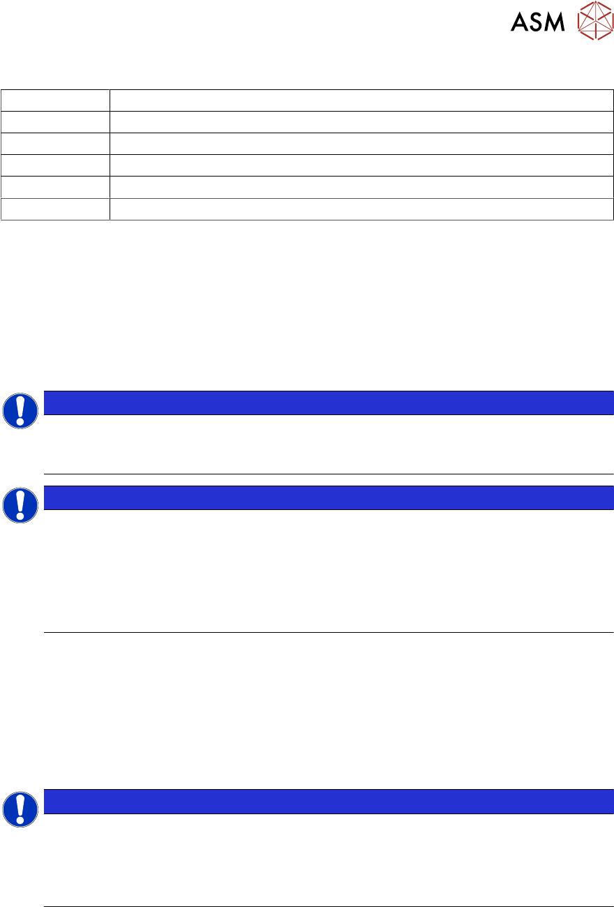
Fig.306: Cutter tool
1. Cutter tool
2. Cutter openings
3. Fiber optic cable
CAUTION!
Only use each cutter opening once
Make sure that each cutter opening is
only used once. The quality of the cut
cannot be guaranteed if it is used more
than once.
.
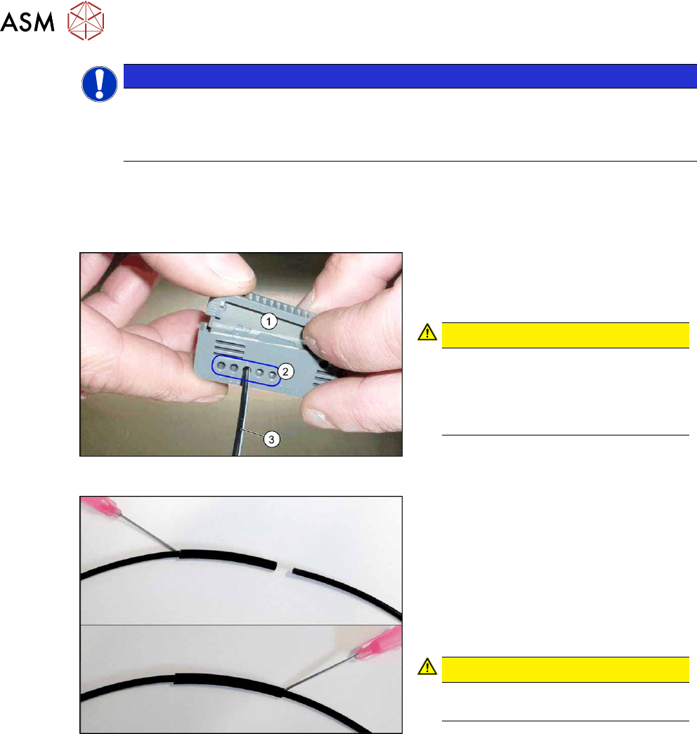
Fig.307: Repairing the fiber optic cables
► Slide both ends of the fiber optic cable
into the repair hose until they touch
each other.
► Fix the repair hose into place with Loc-
tite 406.
This adhesive is used to fix the fiber
optic cable in the hose. The two ends
of the fiber optic cable are not fixed to
one another with adhesive.
CAUTION!
Highly viscous instant glue
Use gloves and a dosage tip.
.
Further installation is performed by following the above instructions in the reverse order. Also
observe the following instructions:
► Check the setting for the transmitter/receiver and correct if necessary.
7.8.3 "Checking the laser light barrier" [}222]
7.8.4 "Correcting the Laser Light Barrier Setting" [}225]
► Calibrate the sensors of the PCB conveyor.
► Check the display on the fiber optic sensor. The value shown must be over 100. Check the
value for the various conveyor widths (red = output / green = input).
► Mark the optical system and the fiber optic cable at the fiber optic sensor with the glue dot
supplied. The glue dot indicates that the fiber optic cable has already been repaired and that a
replacement is compulsory at the next defect.
7 Conveyor
7.8 Laser light barriers, fiber optic cable and PCB sensors
Service Manual SIPLACE X-Series S (from Hxxxx) 01/2021 233
7.8.7 Replacing the Fiber Optic Cable Sensor
Parts, equipment and tools
●
Fiber optic sensor WLL180T-M pre-programmed SXa [03093294-xx] (master) or
Fiber optic sensor WLL180T-F pre-programmed SXa [03093295-xx] (slave)
●
If needed: screwless end stop 6mm 249-116 [00356396‑xx]
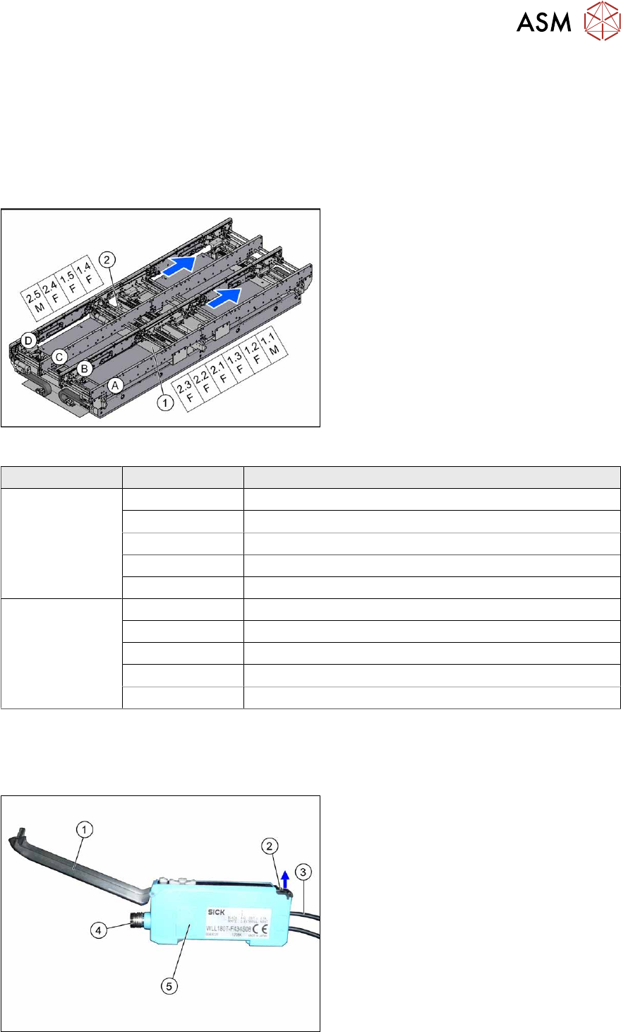
Overview
Fig.308: Overview of fiber optic cable sensor
The fiber optic cable sensors are located at
locations 1 and 4, under the covers of the
conveyor control(1)
and(2).
The sensors for the input conveyor, place-
ment area 1 and intermediate conveyor can
be found at (1)
.
The sensors for placement area 2 and the
output conveyor can be found at (2)
.
The fiber optic cable sensors are separated
into master (M) and slave (F).
The receiver is always at the top of the
sensors and the transmitter at the bottom.
The transmitters are located on sides B and D.
The receivers are located on sides A and C.
Conveyor lane Designation Area
Lane 1 1.1 Input belt
1.2 Placement area 1
1.3 Intermediate belt
1.4 Placement area 2
1.5 Output belt
Lane 2 2.1 Input belt
2.2 Placement area 1
2.3 Intermediate belt
2.4 Placement area 2
2.5 Output belt
The master synchronizes the slaves to prevent any mutual interference. This is conducted via a side
connection to the neighboring sensor. For this reason, do not simply lift the sensors up and off the strip.
Each sensor has two fiber optic cables connected (transmitter/receiver), which belong to the same
conveyor belt (segment).
Fig.309: Fiber optic cable sensor
1. Cover
2. Locking the fiber optic cables
top = open
bottom = closed
3. Fiber optic cable
4. Electrical connection
5. Electrical connection to neighboring
receiver (under the plastic cover)