00198829-01_SM_X-Series-S_Hxxxx_EN.pdf - 第34页
2 Basic Machine 2.7 Stationary component camera 34 Service Manual SIPLACE X-Series S (from Hxxxx) 01/2021 2.7.2 Troubleshooting for stationary cameras Fig.23: Maintenance menu NOTICE! Camera Connections The Camera Con…
2 Basic Machine
2.7 Stationary component camera
Service Manual SIPLACE X-Series S (from Hxxxx) 01/2021 33
2.7 Stationary component camera
2.7.1 Replacing the stationary component camera
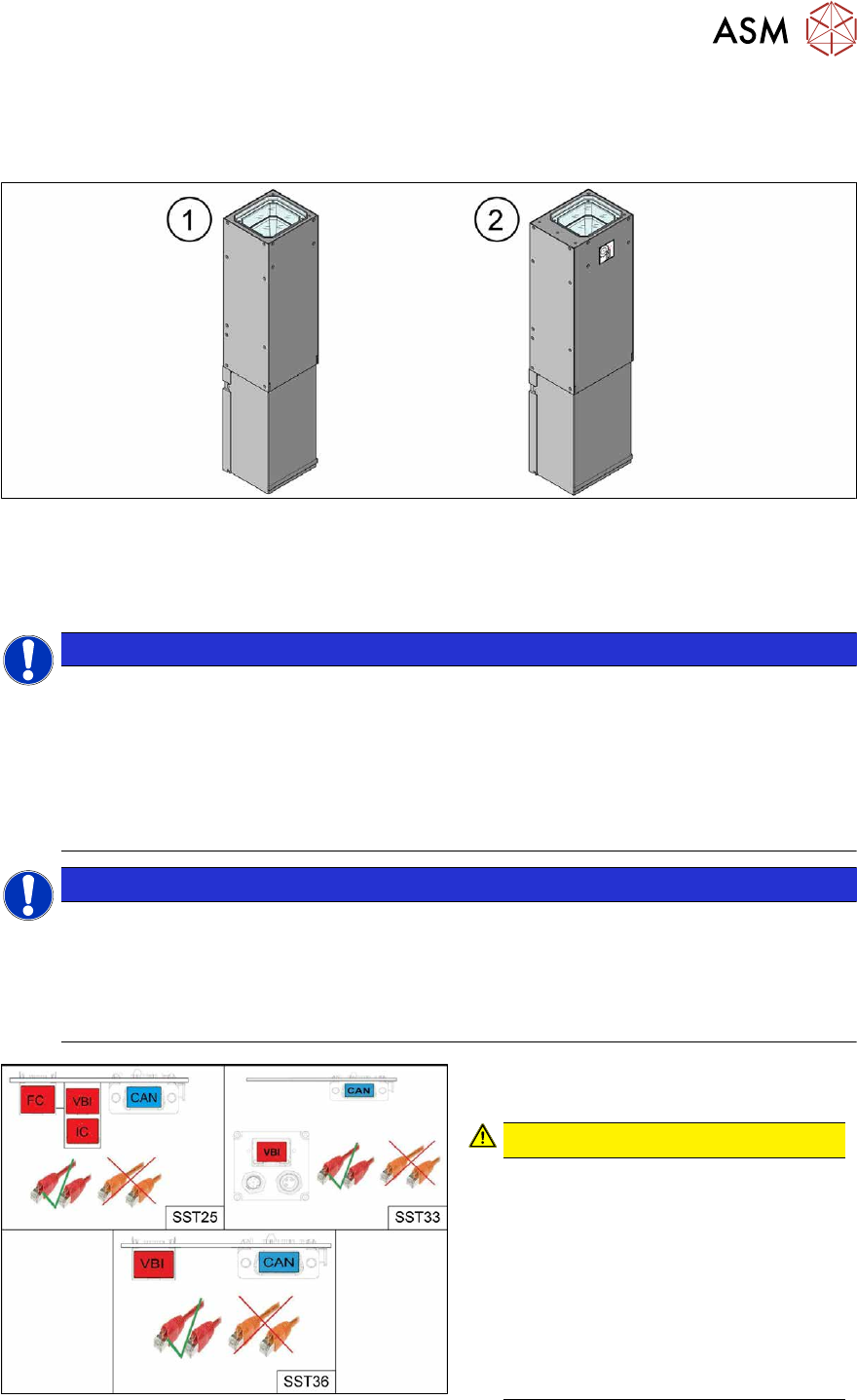
Fig.21: Stationary cameras SST25(1) and SST33(2)
Read the assembly instructions for this:
●
Assembly instructions "SIPLACE X-Series S - Stationary Camera 25/33 GigE" [DE+EN:
00197710‑xx]
NOTICE
Subsequent installation or conversion of stationary cameras
Observe the following documents, where necessary:
► "Incorrectly labeled spacers for stationary cameras" [DE: TI2014-02D04] [EN:
TI2014-02E04]
During retrofitting or conversion of stationary cameras or "Smart Pin Support Q10"
magazines, pay attention to correct fitting of the spacers.
► Assembly instructions "SIPLACE X-Series S - Smart Pin Support" [DE+EN: 00197394-xx]
NOTICE
Camera adaptor
You may need to fit an IC camera adaptor assembly (see assembly instructions).
► Location 1 and 4: IC camera adaptor assembly SP4 SX4a [03099004-xx] (only for IC)
► Location 2 and 3: IC camera adaptor assembly SX4a [03099054-xx] (for IC, FC and
coplan)
Fig.22: Cables
From machine number Hxxxx, the stationary
cameras fitted will have GigE.
CAUTION!
Pay attention to the correct cabling of
the stationary cameras.
Never install a GigE camera in an
older machine (up to machine number
Gxxxx) with Hotlink interface as this
will result in destruction of the camera!
The Hotlink interface can be identified
by the orange cables.
The GigE interface can be identified by
the red cables.
.
2 Basic Machine
2.7 Stationary component camera
34 Service Manual SIPLACE X-Series S (from Hxxxx) 01/2021
2.7.2 Troubleshooting for stationary cameras
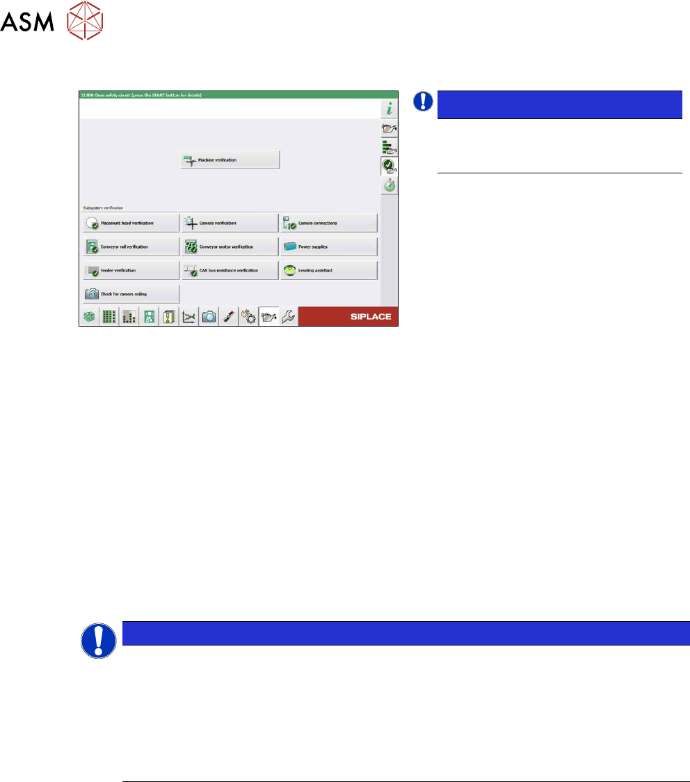
Fig.23: Maintenance menu
NOTICE!
Camera Connections
The Camera Connections can be
checked in the maintenance menu.
.
Error / problem
●
Errors arise during nozzle scanning, even though the nozzle has already been checked to en-
sure that it is clean.
●
During camera verification (FCCS), it is difficult to achieve the necessary illumination.
●
Increased component rejection rate, particularly with low-contrast components.
Cause
If one or more of these errors occurs, the cause may be a dirty camera.
Solution
► Clean the stationary cameras. For further information, please read the technical information "
Cleaning SIPLACE Vision camera systems" [DE:TI2014‑10D09] [EN:TI2014‑10E09].
► Please also observe the maintenance instructions for your machine.
NOTICE
"Check camera soiling" function
In station software 712.1, a new function, "Check camera soiling" was introduced. This re-
quires additional measuring tools.
For more information, please read the following documents:
► Technical information "New functions for camera verification (FCCS_di-
gital)" [DE:TI2019‑02D06] [EN:TI2019‑02E06]
► User guide "Camera calibration FCCS digital" [DEEN:00196449‑xx]
Problem
●
Error message 37752: "The LED test of the camera illumination failed" at GigE cameras
Solution
► Please contact the SIPLACE service team for more information.
Give them the following reference number: TI2015-08V03.
2 Basic Machine
2.7 Stationary component camera
Service Manual SIPLACE X-Series S (from Hxxxx) 01/2021 35
2.7.3 PCBs Stationary Cameras
2.7.3.1 Vision LED Controller VLC25/33 GigE DTC
●
Vision LED Controller VLC33 GigE DTC [03117981-xx]
●
Vision LED Controller VLC25 GigE DTC [03117587-xx]
These two circuit boards are in principle identical. The VLC25 board however, also has the con-
nectors X21 and X22
The circuit boards are part of the stationary camera SST25/33 GigE.
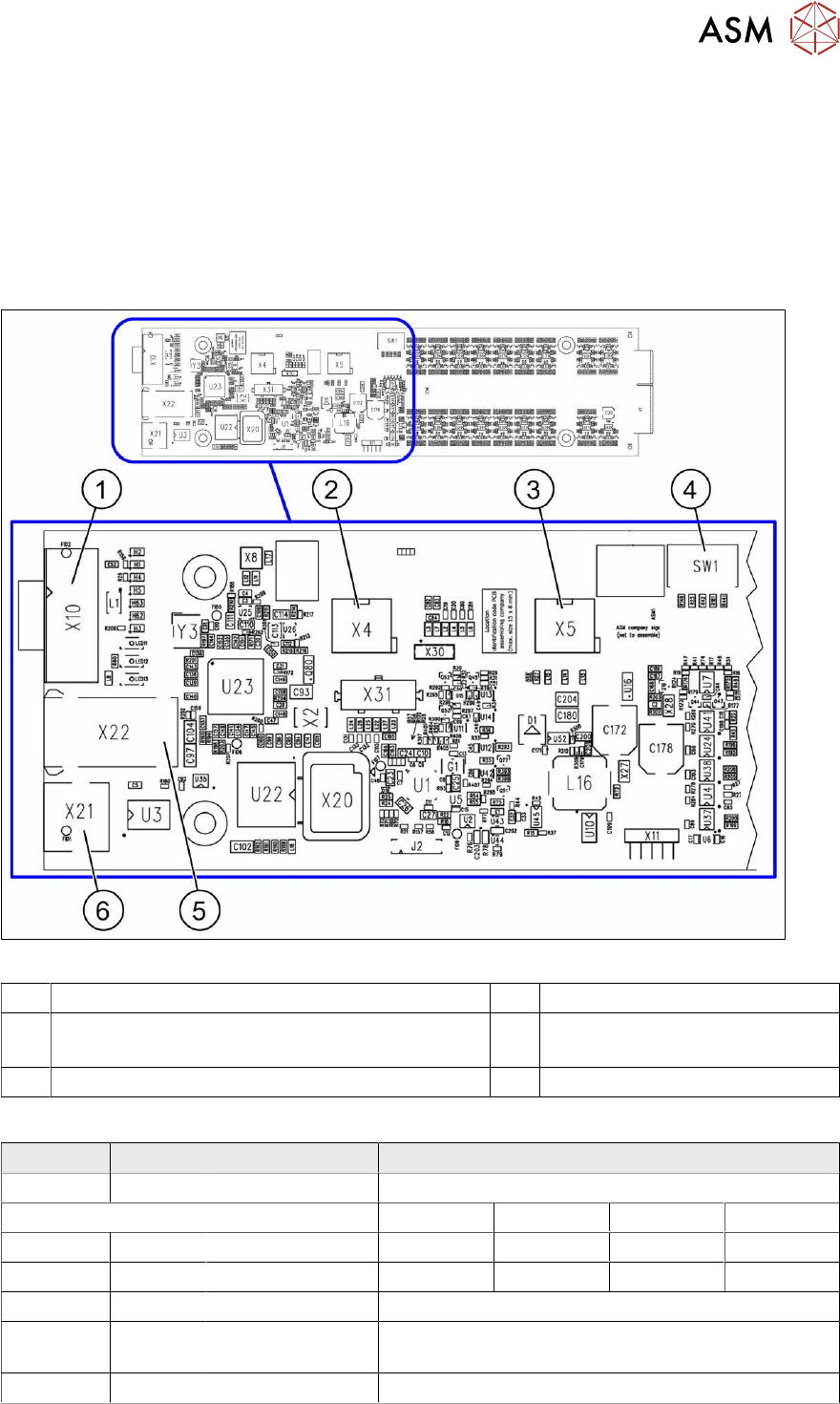
Fig.24: Vision LED Controller VLC25 GigE DTC [03117587-xx]
1 CAN bus 2 X4: Cable for power supply
3 X5: Cable for power supply, bridge to FC camera
(Not used in TX-Series)
4 DIP switch SW1 (see below)
5 Connector X22 (VLC25 only) 6 Connector X21 (VLC25 only)
DIP switch S1 [03117587-xx] [03117981-01]
Switch Status Signal name Description
S1.1 OFF VCU_CODE OFF: normal operation, ON: Reset
Location 1 Location 2 Location 3 Location 4
S1.2 ON/OFF GANTRY_ID_0 *) OFF ON OFF ON
S1.3 ON/OFF GANTRY_ID_1 *) OFF OFF ON ON
S1.4 OFF SMD_LED OFF: standard LED, ON: SMD LED
S1.5 OFF CAN_H OFF: with CAN terminator
ON: without CAN terminator
S1.6 ON/OFF CAN_GROUP ON: IC camera , OFF: FC camera
*) Set the location at which the stationary camera is fitted.