00198829-01_SM_X-Series-S_Hxxxx_EN.pdf - 第348页
9 Component feeding 9.4 Docking Station for Component Trolley 348 Service Manual SIPLACE X-Series S (from Hxxxx) 01/2021 Overview 1 Fig.493: FCU on docking station 1. Feeder control unit 3 3 1 3 2 Fig.494: FCU overview…
9 Component feeding
9.4 Docking Station for Component Trolley
Service Manual SIPLACE X-Series S (from Hxxxx) 01/2021 347
9.4.8 Replacing the Feeder Control Unit (FCU)
Parts
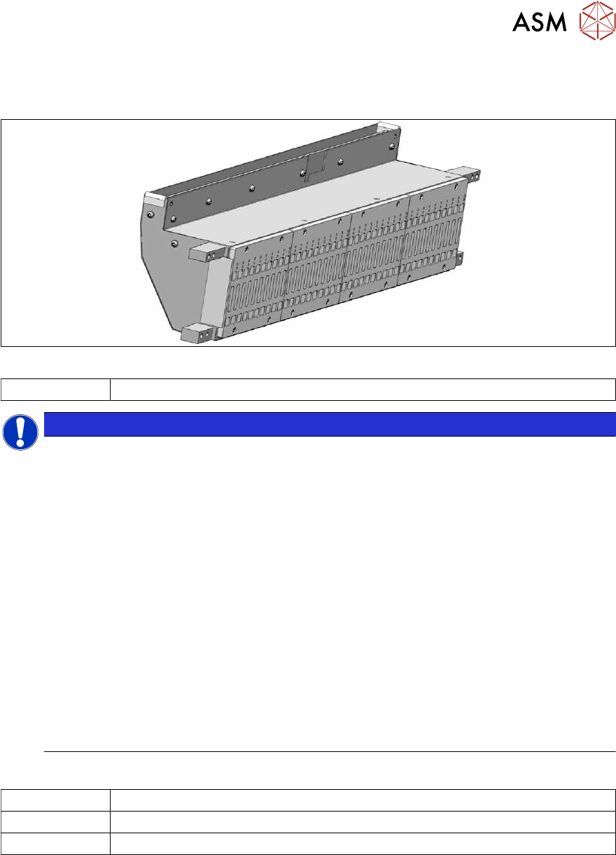
Fig.492: FCU
03059623Sxx X-FCU/ X-Series (replaces: [03020068-xx])
NOTICE
Observing the technical information
Observe the technical information "Replacing the FCU" (SIPLACE X-Series, SX4/DX4,
X‑SeriesS, Docking Station) [DE: TI2014-11D15
] [EN: TI2014-11E15]:
Since June 2010, the "nozzle changer control" and the "cutter control" have been integrated
into the "X-FCU / SIPLACE X-Series" [03059623-xx]. The CAN nodes are therefore no
longer used.
The assembly is, however, not 100% downwards compatible with regard to the mechanical
installation.
► Docking station for component trolley SIPLACE [00116933‑xx] (SIPLACE X-
Series)
Any remaining old "FCU SIPLACE X-Series" [03020068‑xx] should be used for the
docking station for SIPLACE X‑Series component trolleys [00116933‑xx] and for spare
part disposal at these docking stations.
In order to use the new "X‑FCU SIPLACE X-Series" [03059623Sxx] on the "docking
station X [00116933‑xx]", you need to use an additional "cable set X-FCU for docking
station X [00116933‑xx]" [03098897‑xx].
Since March 2013, all new deliveries of the docking station for SIPLACE X-Series
have the new FCU.
Equipment and tools
00353832-xx Allen key set
Wire cutters
Cable tie
9 Component feeding
9.4 Docking Station for Component Trolley
348 Service Manual SIPLACE X-Series S (from Hxxxx) 01/2021
Overview
1
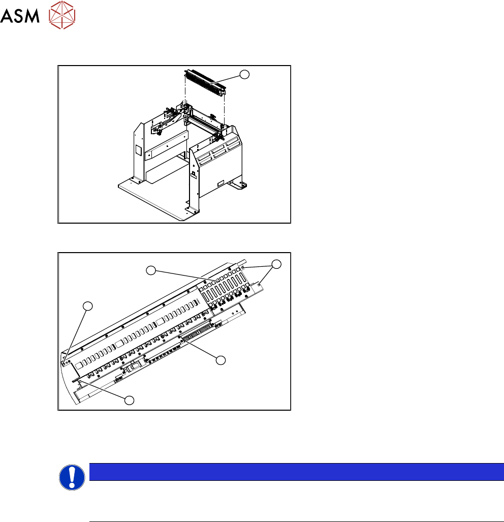
Fig.493: FCU on docking station
1. Feeder control unit
3
3
1
3
2
Fig.494: FCU overview
1. FCU assembly
2. Terminal strip
3. Screws fastening the FCU
Depending on the version, there will be
four or six screws.
Removal
NOTICE
Example shown as diagram
The tasks to be performed are described using the example of the SIPLACE TX1 V1. The
procedure for the docking station is the same.
► Switch off the machine, disconnect it from the power supply and secure it to prevent
unauthorized reactivation.
1.2 "Preparatory work..." [}16]
► Dismantle and remove the feeder unlocking device.
9.4.7 "Replacing the 40-fold feeder unlocking device" [}346]
9 Component feeding
9.4 Docking Station for Component Trolley
Service Manual SIPLACE X-Series S (from Hxxxx) 01/2021 349
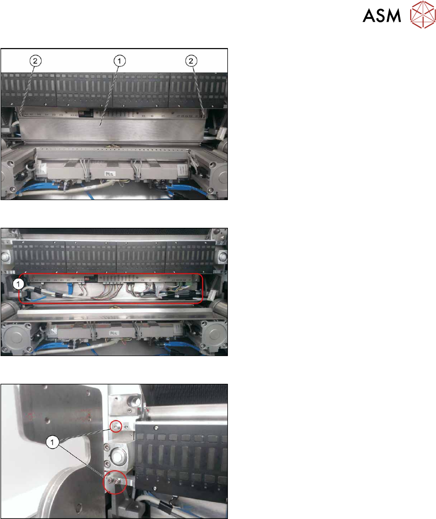
Fig.495: FCU cover plate
► Remove the two screws(2) fastening
the FCU cover plate(1)
.
Fig.496: Connections
► Unplug all electrical connections from
the terminal strip of the FCU.
Fig.497: Fastening screws
► Remove the screws(1) fastening the
FCU on both sides.
Depending on the version, there will be
four or six screws.
► Carefully lever the FCU out of the locating pins.
► Remove the earth terminal.
Installation
► Set the DIP switches on the FCU.
► Refit the cover plate and the FCU.
► Place the connection cable in the recess and carefully push in the new FCU. Make sure you
do not pinch any cables.
► Pull the ends of the cables out from under the terminal strip.
► Plug in all electrical connections as labeled on the terminal strip.
Further installation is performed by following the above instructions in the reverse order.