00198829-01_SM_X-Series-S_Hxxxx_EN.pdf - 第138页
6 Gantries 6.4 Trailing cable and printed circuit boards 138 Service Manual SIPLACE X-Series S (from Hxxxx) 01/2021 DIP switch S1 The DIP S1 switch settings depend on the board version: Dip switch S1 [03115454-01] ON OFF…
6 Gantries
6.4 Trailing cable and printed circuit boards
Service Manual SIPLACE X-Series S (from Hxxxx) 01/2021 137
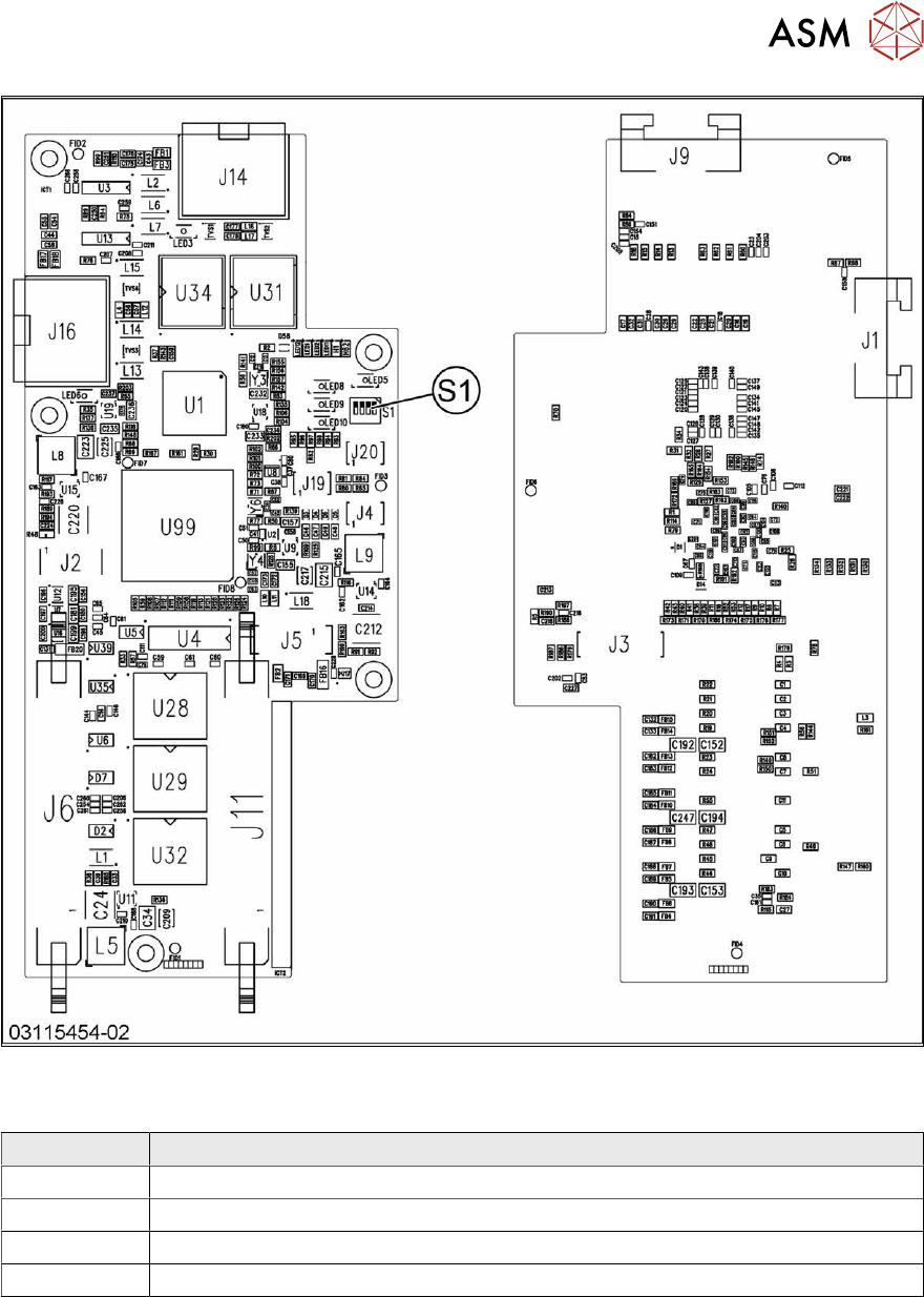
Fig.177: Vision Head Interface
Press-fit connections
Connector Description
J14 CAM1 – PCB camera
J16 CAM2 – component camera
J6, J11 Trailing cable
J5 Power supply
6 Gantries
6.4 Trailing cable and printed circuit boards
138 Service Manual SIPLACE X-Series S (from Hxxxx) 01/2021
DIP switch S1
The DIP S1 switch settings depend on the board version:
Dip switch S1 [03115454-01]
ON OFF Comments
1 ON Spread OFF/ON
2 See text X-Series S: ON
All other machines: OFF
3 See text X-Series S: OFF
All other machines: ON
4 OFF CAN-R ON/OFF
DIP switch S1 [03115454-02 und -03]
ON OFF Comments
1 See text X-Series S: OFF
All other machines: ON
2 OFF Reserve
3 ON EEPROM
4 OFF CAN-R ON/OFF
Removal
► Switch off the machine, disconnect it from the power supply and secure it to prevent
unauthorized reactivation.
1.2 "Preparatory work..." [}16]
► If there is a cover above the boards, dismantle it.
6.4.1 "Replacing the cover on the boards" [}118]
► Unplug all electrical connections to the VHI. You may want to mark the positions of these con-
nections to make clear assignment easier later on.
► Remove the screws fastening the VHI and then remove the board.
Installation
Follow the removal instructions in reverse order for installation. Also observe the following instruc-
tions:
► Set the correct gantry ID. Take the setting from the dismantled board.
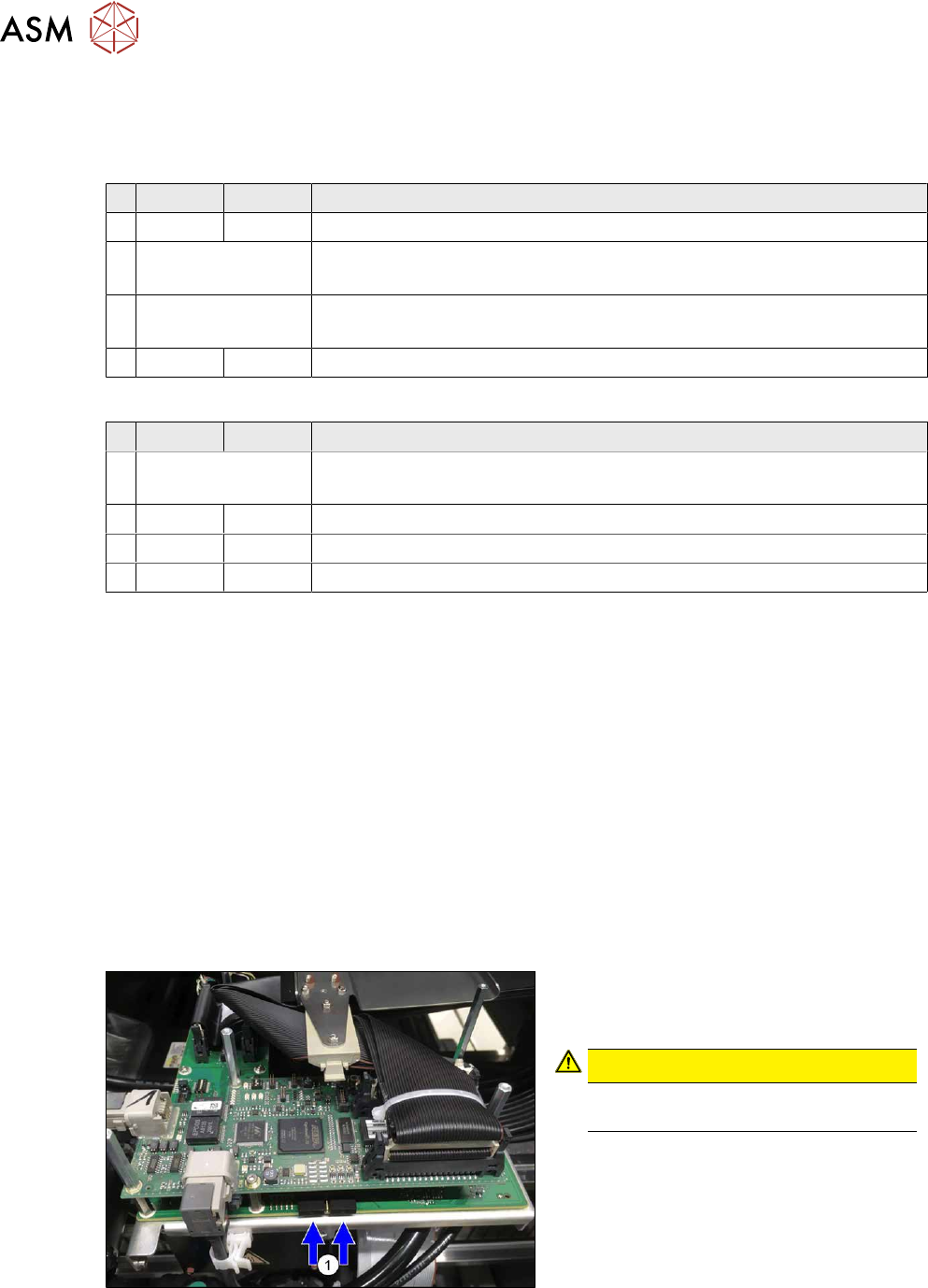
Fig.178: Dummy plug
► Secure the connector X1on the head
interface, if present, with two dummy
plugs(1)
.
CAUTION!
Without the dummy plugs, there is a
risk of short circuit at the board cover!
.
► Checking the embedded software and performing a download if needed (see LINK).
10.1 "eSW Download (SW 70x)" [}379]

6 Gantries
6.4 Trailing cable and printed circuit boards
Service Manual SIPLACE X-Series S (from Hxxxx) 01/2021 139
Troubleshooting
Error:
●
Image transmission errors occur at cameras of type GigE.
●
Potential error message:
FM 33332: image transmission to SIPLACE Vision computer interrupted.
Solution
●
Check the DIP switches for the VHI. Pay attention to the function state of
the board.
Error:
●
When starting the station software, cameras of type GigE are sometimes
not recognized.
●
Potential error messages:
FM 33378: unable to address camera (242).
FM 33209: unable to initialize camera with specified sensor ID.
FM 31904: unable to initialize machine hardware.
Solution
●
Contact the SIPLACE Service team for details.
Error:
●
This would lead to communication errors with one or more cameras.
●
There are communication errors with one or more cameras.
Solution
●
Please contact the SIPLACE service team for more information.
Give them the following reference number: TI2019-11V01.