00198829-01_SM_X-Series-S_Hxxxx_EN.pdf - 第35页
2 Basic Machine 2.7 Stationary component camera Service Manual SIPLACE X-Series S (from Hxxxx) 01/2021 35 2.7.3 PCBs Stationary Cameras 2.7.3.1 Vision LED Controller VLC25/33 GigE DTC ● Vision LED Controller VLC33 GigE D…
2 Basic Machine
2.7 Stationary component camera
34 Service Manual SIPLACE X-Series S (from Hxxxx) 01/2021
2.7.2 Troubleshooting for stationary cameras
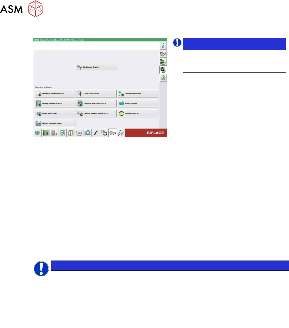
Fig.23: Maintenance menu
NOTICE!
Camera Connections
The Camera Connections can be
checked in the maintenance menu.
.
Error / problem
●
Errors arise during nozzle scanning, even though the nozzle has already been checked to en-
sure that it is clean.
●
During camera verification (FCCS), it is difficult to achieve the necessary illumination.
●
Increased component rejection rate, particularly with low-contrast components.
Cause
If one or more of these errors occurs, the cause may be a dirty camera.
Solution
► Clean the stationary cameras. For further information, please read the technical information "
Cleaning SIPLACE Vision camera systems" [DE:TI2014‑10D09] [EN:TI2014‑10E09].
► Please also observe the maintenance instructions for your machine.
NOTICE
"Check camera soiling" function
In station software 712.1, a new function, "Check camera soiling" was introduced. This re-
quires additional measuring tools.
For more information, please read the following documents:
► Technical information "New functions for camera verification (FCCS_di-
gital)" [DE:TI2019‑02D06] [EN:TI2019‑02E06]
► User guide "Camera calibration FCCS digital" [DEEN:00196449‑xx]
Problem
●
Error message 37752: "The LED test of the camera illumination failed" at GigE cameras
Solution
► Please contact the SIPLACE service team for more information.
Give them the following reference number: TI2015-08V03.
2 Basic Machine
2.7 Stationary component camera
Service Manual SIPLACE X-Series S (from Hxxxx) 01/2021 35
2.7.3 PCBs Stationary Cameras
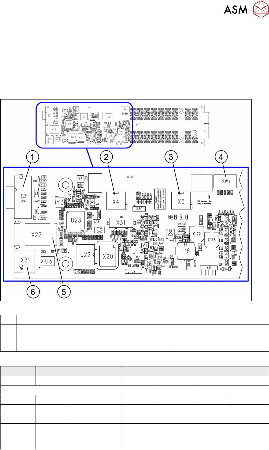
2.7.3.1 Vision LED Controller VLC25/33 GigE DTC
●
Vision LED Controller VLC33 GigE DTC [03117981-xx]
●
Vision LED Controller VLC25 GigE DTC [03117587-xx]
These two circuit boards are in principle identical. The VLC25 board however, also has the con-
nectors X21 and X22
The circuit boards are part of the stationary camera SST25/33 GigE.
Fig.24: Vision LED Controller VLC25 GigE DTC [03117587-xx]
1 CAN bus 2 X4: Cable for power supply
3 X5: Cable for power supply, bridge to FC camera
(Not used in TX-Series)
4 DIP switch SW1 (see below)
5 Connector X22 (VLC25 only) 6 Connector X21 (VLC25 only)
DIP switch S1 [03117587-xx] [03117981-01]
Switch Status Signal name Description
S1.1 OFF VCU_CODE OFF: normal operation, ON: Reset
Location 1 Location 2 Location 3 Location 4
S1.2 ON/OFF GANTRY_ID_0 *) OFF ON OFF ON
S1.3 ON/OFF GANTRY_ID_1 *) OFF OFF ON ON
S1.4 OFF SMD_LED OFF: standard LED, ON: SMD LED
S1.5 OFF CAN_H OFF: with CAN terminator
ON: without CAN terminator
S1.6 ON/OFF CAN_GROUP ON: IC camera , OFF: FC camera
*) Set the location at which the stationary camera is fitted.
2 Basic Machine
2.8 Nozzle Changers and Reject Boxes
36 Service Manual SIPLACE X-Series S (from Hxxxx) 01/2021
2.8 Nozzle Changers and Reject Boxes
See also
2 9.2 "COT insert" [}312]
2.8.1 Nozzle Changers and Nozzle Stations - Overview
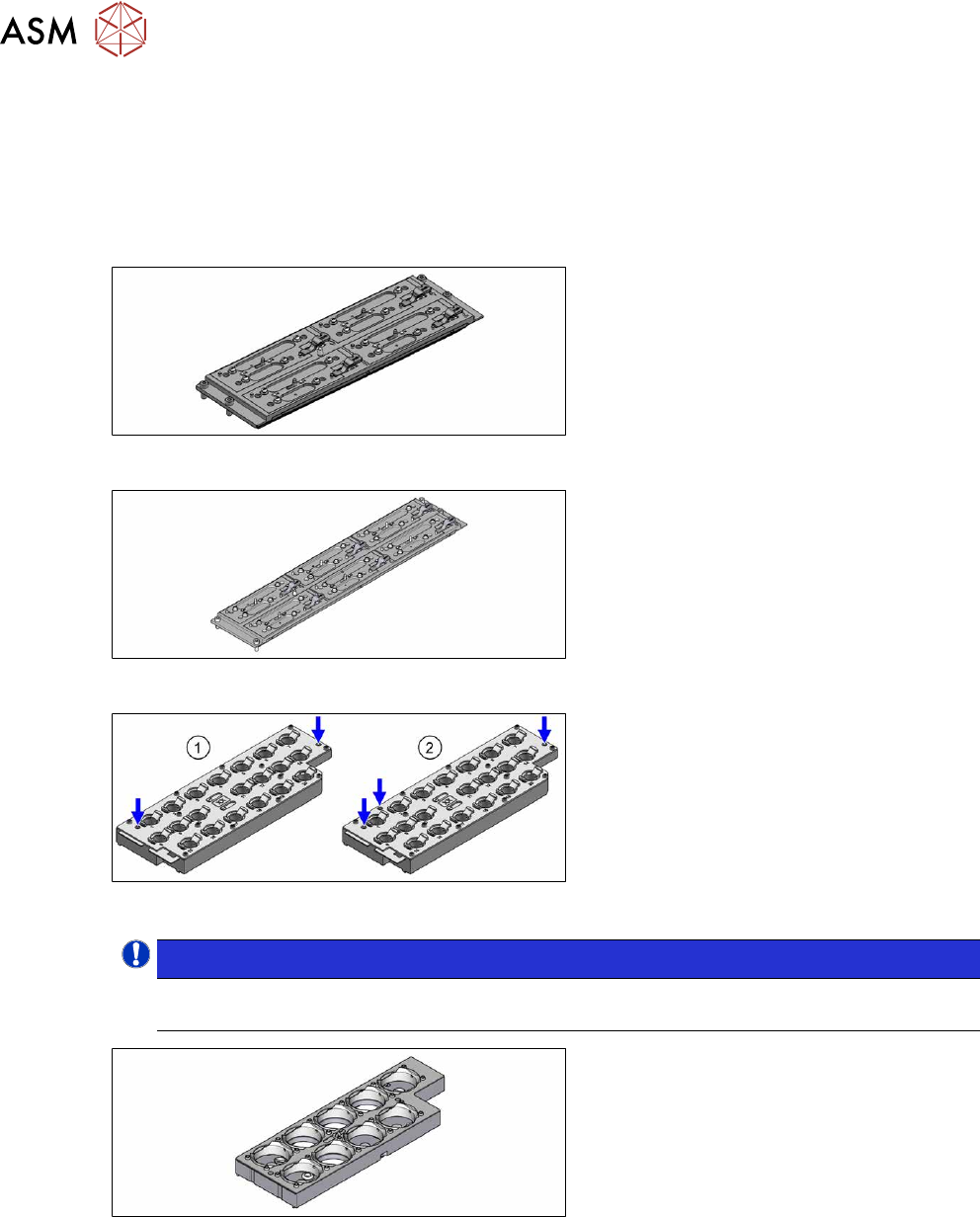
Fig.25: Nozzle changer CPx short [03147925‑xx]
Nozzle changer basic structure (short
design) for all CPx placement heads
Fig.26: Nozzle changer, long [03147324‑xx]
Standard nozzle changer, long
[03147324‑xx] for six magazines
Fig.27: 20xx magazine with two and three fiducials
Magazine for 20 nozzles of 20 xx series
●
Magazine with two fiducials
[03135469‑xx]
●
Magazine with three fiducials
[03226630‑xx]
NOTICE!
From SW713.1 the magazine will need to be recalibrated using three fiducials when changing
the magazine. This step will no longer be necessary from SW714.
.
Fig.28: Magazine 28xx [03065782-xx]
Magazine for nozzles of 28 xx series