00198829-01_SM_X-Series-S_Hxxxx_EN.pdf - 第180页
7 Conveyor 7.4 Conveyor Drive 180 Service Manual SIPLACE X-Series S (from Hxxxx) 01/2021 Removal CAUTION Toothed belt ► Make sure that the toothed belt is not folded! ► Dismantle the conveyor drive. For more information,…
7 Conveyor
7.4 Conveyor Drive
Service Manual SIPLACE X-Series S (from Hxxxx) 01/2021 179
7.4.4 Replacing the toothed belt (conveyor drive)
Parts, equipment and tools
●
Synchroflex toothed belt 6 AT3/150 [00355553-xx]
●
Bearing for hexagonal shaft SXa (plastic bearing) – pack of 10 [03092024-xx]
●
Sealing varnish Loctite 241 [02101037-xx]
Overview
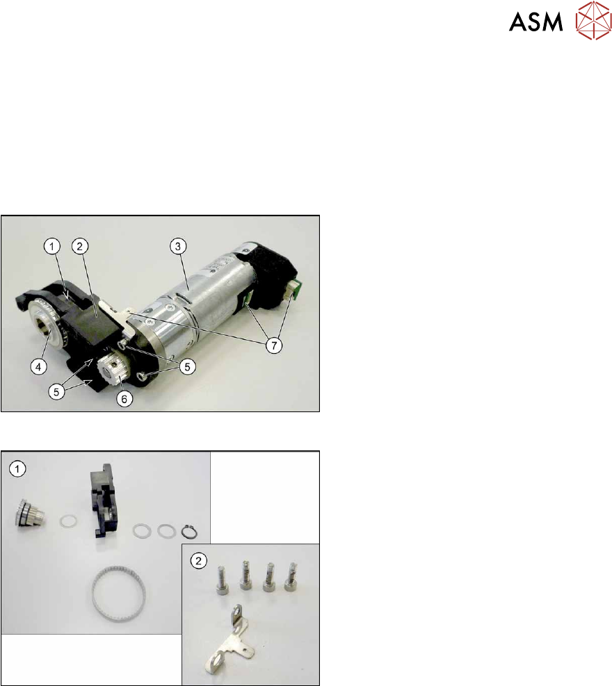
Fig.234: Conveyor drive
1. Toothed belt on conveyor drive
2. Drive bracket
3. Motor
4. Drive shaft
5. Four motor fastening screws in the
drive bracket
6. Motor shaft
7. Electrical connections (incl. shield con-
nection)
Fig.235: Drive shaft and bracket
1. Drive shaft with drive bracket, washers,
circlip and toothed belt
2. Motor fastening screws and shield con-
nection

7 Conveyor
7.4 Conveyor Drive
180 Service Manual SIPLACE X-Series S (from Hxxxx) 01/2021
Removal
CAUTION
Toothed belt
► Make sure that the toothed belt is not folded!
► Dismantle the conveyor drive. For more information, read section 7.4.1 "Replacing the con-
veyor drive" [}173].
NOTICE
Make a note of the order
You may want to make a note of the order in which the following parts are, to make it easier
to refit them later on. The number of washers may vary. Make sure that you fit the exact
number of these in the exact places.
► Open the circlip.
► Take off the washers.
► Pull the drive shaft out of the housing. You may need to apply slightly more force than usual to
remove the drive shaft.
► Remove the toothed belt.
Installation
Follow the removal instructions in reverse order for installation. Also observe the following instruc-
tions:
► Make sure that the toothed belt is not folded or otherwise damaged!
► Make sure that the toothed belt is not rubbed against anything.
► Tension the toothed belt with 10 to 15 Hz.
► Secure the four screws fastening the conveyor drive to the drive bracket with Loctite 241 and
tighten these with a torque of 0.7 Nm
.
► Replace any opened cable ties.
► Observe the installation instructions for the conveyor drive.
7 Conveyor
7.5 Width Adjustment, Clamps and Cylinder Unit
Service Manual SIPLACE X-Series S (from Hxxxx) 01/2021 181
7.5 Width Adjustment, Clamps and Cylinder Unit
NOTICE
Exemplary description
Provided identical parts are present, the width adjustment will be described using the exam-
ple of a dual conveyor.
The procedure is the same for a single conveyor.
Any relevant differences will be mentioned explicitly.
7.5.1 Overview of width adjustment
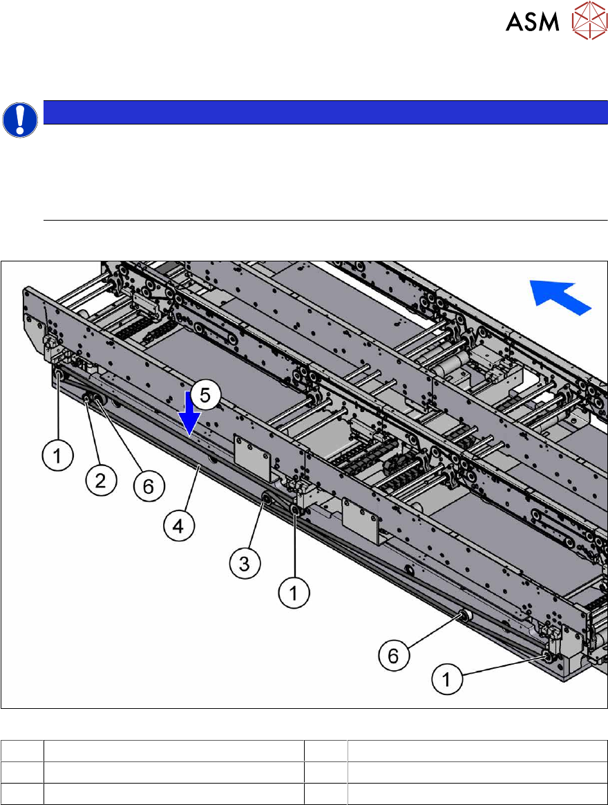
Fig.236: Overview of width adjustment
1 Cylinder units 2 Width adjustment drive
3 Movable idler pulley 4 Toothed belt of width adjustment
5 Measurement point for belt tension 6 Idler pulley