00198829-01_SM_X-Series-S_Hxxxx_EN.pdf - 第295页
9 Component feeding 9.1 Cutter Service Manual SIPLACE X-Series S (from Hxxxx) 01/2021 295 Follow the removal instructions in reverse order for further installation. Also observe the following instructions: ► Make sure th…
9 Component feeding
9.1 Cutter
294 Service Manual SIPLACE X-Series S (from Hxxxx) 01/2021
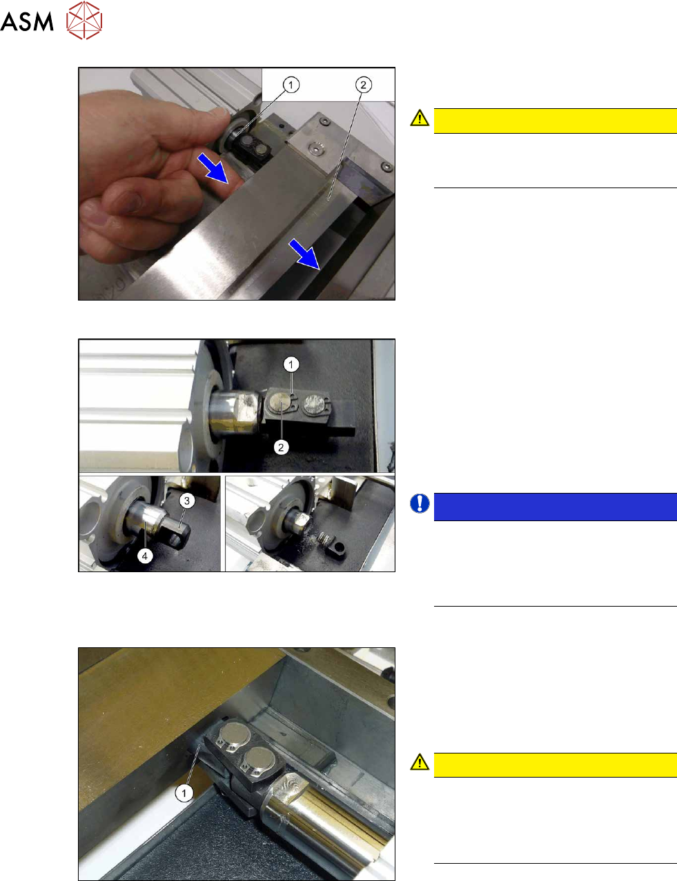
Fig.399: Movable blade
► Loosen the movable blade(2) from the
piston(1)
of the short-stroke cylinder.
CAUTION!
Risk of injury!
There is a risk of injuring yourself on
the cutting edge of the blades.
.
Fig.400: Removing the articulated joint
► Remove the circlip (1).
► Push the piston rod a little into the
short-stroke cylinder and rotate the ar-
ticulated joint by 90degrees.
► Push the bolt(2) out of the articulated
joint.
► Unscrew the remaining articulated joint
adapter(3)
from the piston(4).
NOTICE!
The adapter is secured with locking
varnish (Loctite no. 243). You will need
somewhat more strength than usual to
loosen it.
Hold against it with a spanner wrench.
.
Installation
Fig.401: Installing the articulated joint
► Screw the articulated joint into the
short-stroke cylinder with a torque of
22Nm. Make sure that the joint (1) is
horizontal so that it fits into the recess
in the moveable blade. Secure the
screw with Loctite243
.
CAUTION!
Installation position
The articulated joint must be hori-
zontal. If not, the blades could be dis-
torted, which will then cause the joint
to break.
.
► Screw the articulated joint to the moveable blades. Tighten the screws to a torque of 6 Ncm.
9 Component feeding
9.1 Cutter
Service Manual SIPLACE X-Series S (from Hxxxx) 01/2021 295
Follow the removal instructions in reverse order for further installation. Also observe the following
instructions:
► Make sure that the bolts are greased (Klüber BEM 34-132).
► Secure the screws with Loctite 243.
► Insert the new screw caps. Remove the protruding plastic residues with a knife.
► Connect the compressed air hoses to the cylinder in the correct allocation.
► Check the gap between the leading edge of the wiper and the "empty-tape baffle, inside".
NOTICE
If the tapes are not cut correctly.
If the tapes are not cut correctly, even though the switching points have been set properly
and the short-stroke cylinder has been exchanged - complete with the one-way restrictor -
the cause of the problem may be:
► Incorrect compressed air level
► Leaking compressed air connection or Y-socket union
9.1.9 Replacing the short-stroke cylinder
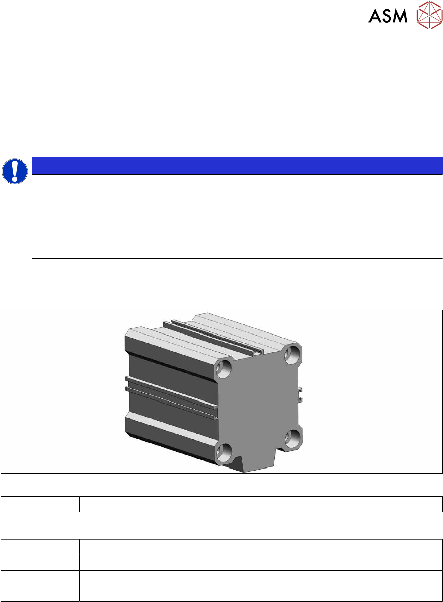
Parts
Fig.402: Short stroke cylinder
03038587-xx Short-stroke cylinder 50x40 ECDQ2B50-0040-CEJ00119
Equipment and tools
00334892‑xx Loctite 243
00353832-xx Allen key set
Wire cutters
Cable tie
Removal
► Switch off the machine, disconnect it from the power supply and secure it to prevent
unauthorized reactivation.
1.2 "Preparatory work..." [}16]
► Remove the cutter from the machine.
9.1.4 "Replacing the Cutter on the COT Insert [03066690-xx]" [}285]
► Remove the articulated joint from the short-stroke cylinder (5).
9.1.8 "Replacing the articulated joint on the short-stroke cylinder" [}292]
9 Component feeding
9.1 Cutter
296 Service Manual SIPLACE X-Series S (from Hxxxx) 01/2021
1
6
5
4
3
2
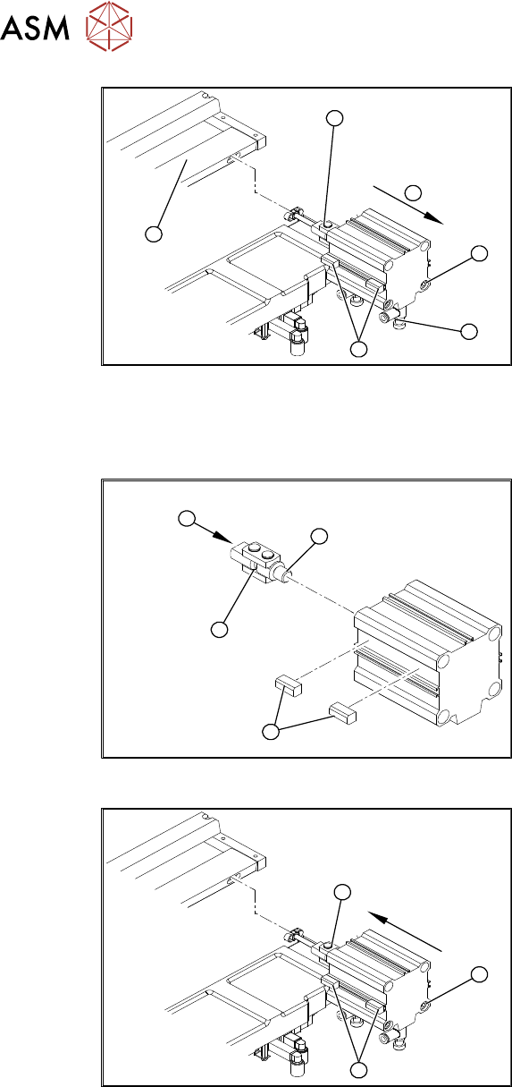
Fig.403: Removing the short-stroke cylinder
► Use a permanent marker to mark the
exact installation position of the proxim-
ity switch (1)
on the short-stroke cylin-
der.
► Remove the screws fastening the two
inductive proximity switches (1)
to the
short-stroke cylinder.
► Remove the compressed air connec-
tions (2)
on the short-stroke cylinder.
You may want to mark their positions to
make clear assignment easier later on.
► Remove the two screws (3) fastening
the short-stroke cylinder.
► Remove the short-stroke cylinder (4)
from the cutter.
Installation
1
4
3
2
Fig.404: Fitting the articulated joint and proximity switches
► Apply a small amount of Loctite243 to
the thread (2)
of the new articulated
joint.
► Screw the articulated joint (1) into the
short-stroke cylinder.
► Turn the articulated joint in its installa-
tion position(3)
.
Once the cylinder is installed, the slot in
the moveable blade prevents the articu-
lated joint from turning.
► Copy the exact installation position of
the proximity switch(4)
onto the new
short-stroke cylinder (e.g. with a feeler
gauge, fine-tipped marker pen).
1
3
2
Fig.405: Fitting the short-stroke cylinder
► Fit the proximity switch (1) precisely in
the position you marked with the per-
manent marker.
► Place the prepared cylinder into the
cutter, in the correct rotary position of
the articulated joint (2)
.
► Fasten the cylinder in this position with
the two screws provided(3)
(Loc-
tite243).
► Connect the compressed air hoses to the cylinder in the correct allocation.
Follow the removal instructions in reverse order for further installation. Also observe the following
instructions:
► Also observe section 9.1.8 "Replacing the articulated joint on the short-stroke cylinder" [}292].
► From SW707.1: set the restrictors (see 9.1.14.1 "Times for setting the restrictor on the cut-
ter" [}308]).