00198829-01_SM_X-Series-S_Hxxxx_EN.pdf - 第314页
9 Component feeding 9.2 COT insert 314 Service Manual SIPLACE X-Series S (from Hxxxx) 01/2021 ► Unplug all electrical and pneumatic connections from the COT insert. Mark the positions of these connections, to make clear …
9 Component feeding
9.2 COT insert
Service Manual SIPLACE X-Series S (from Hxxxx) 01/2021 313
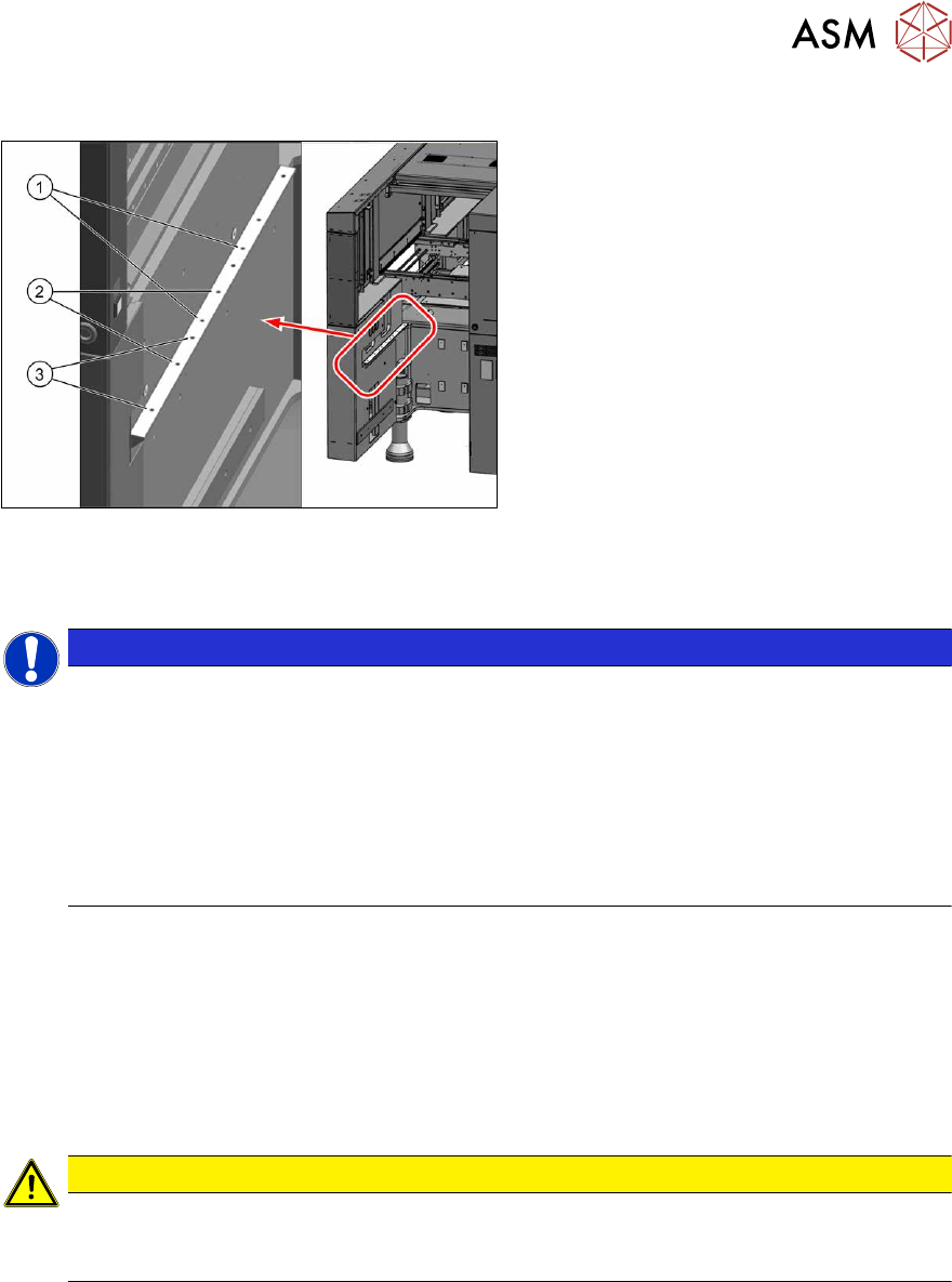
9.2.2 Installation Positions of COT Insert and Manual Table (Table Positions)
Fig.439: Installation positions
The following installation positions apply to
the SIPLACE X-Series S:
1. Installation position 1
COT insert: X4i S
2. Installation position 2
COT insert, manual table: X4i S
3. Installation position 3
COT insert, manual table: X2 S, X3 S,
X4 S
9.2.3 Replacing the COT Insert Assembly
NOTICE
Working on the COT-i without complete removal of this
For some tasks on the COT-i, it may be enough to just pull the COT-i slightly out of the
machine. In this case, follow the procedure for replacement but observe the following
instructions:
► Remove the screws fastening the central unit and the lifting mechanics.
► You usually do not need to disconnect the cable. However, if the cable is too short,
unplug it.
► Slightly pull the COT-i out of the machine.
Parts, equipment and tools
●
SIPLACE X3 S, X4 S: COT insert X4 S [03098442-xx]
or
SIPLACE X4i S: COT insert X4i S [03093204-xx]
●
Circuit diagram X-Series S [00197021-xx] (German/English)
●
Mounting tool [03015976-xx]
●
Suitable lifting device (e.g. hand-operated crane)
CAUTION
Heavy machine part!
The COT insert is heavy. To lift it out, you will need to use the mounting tool and a suitable
lifting device (hand-operated crane etc.).
Removal
► Switch off the machine, disconnect it from the power supply and secure it to prevent
unauthorized reactivation.
1.2 "Preparatory work..." [}16]
► Switch off the compressed air supply
5.2 "Disabling the compressed air supply" [}86]
► Dismantle the nozzle changer.
2.8.3 "Replacing the Nozzle Changer" [}40]
9 Component feeding
9.2 COT insert
314 Service Manual SIPLACE X-Series S (from Hxxxx) 01/2021
► Unplug all electrical and pneumatic connections from the COT insert. Mark the positions of
these connections, to make clear assignment easier later on. The connection cables and
hoses are located behind the COT insert – in the space leading to the machine base (under
the nozzle changer).
► Remove the lower side panel at the location, so that you can lift out the COT insert later on.
5.5 "Dismantling the Lower Side Cover" [}88]
1
1
3
2
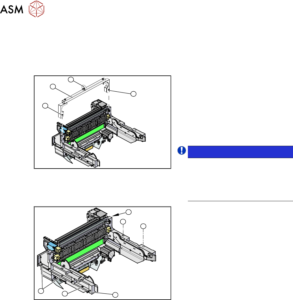
Fig.440: Mounting tool
1. Fixtures
2. Mounting tool
3. Eyelet
► Attach the mounting tool (2) to the fix-
tures provided (1)
on the COT insert.
► Fix the lifting device to the eyelet (3) of
the mounting tool (2)
.
NOTICE!
The COT insert can be installed at dif-
ferent positions in the machine loca-
tion. Mark the position of your COT in-
sert, to ensure that this is sub-
sequently returned to its original posi-
tion.
.
1
1
1
1
2
1
Fig.441: Fastening screws
► Remove the eight fastening screws(1)
of the COT insert.
► Lift the complete COT insert out of the
machine and place it on a suitable sur-
face (four wooden blocks etc.).
► Make sure that you do not damage any
valves, connection cables, hoses etc.
Installation
► Attach the mounting tool to the new COT insert and lift it into the machine, with the help of the
lifting device.
► Reconnect all cables. If required, use the detailed circuit diagrams to help you.
► Move the COT insert into its final position (to the previously marked installation position).
Take care not to damage the cables and hoses.
Further installation is performed by following the above instructions in the reverse order.
9 Component feeding
9.2 COT insert
Service Manual SIPLACE X-Series S (from Hxxxx) 01/2021 315
9.2.4 Replacing the Feeder Control Unit (FCU)
Parts, equipment and tools
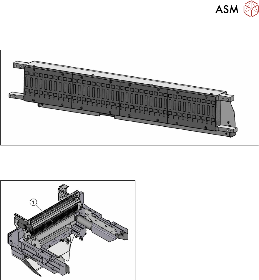
Fig.442: X-FCU V3, X-Series [03170613S01]
●
X-FCU V3, X-Series [03170613Sxx]
Overview
Fig.443: FCU on COTi
1. Feeder control unit (FCU)
The FCU is installed at the locations in the
component trolley feed device.
Removal
► Switch off the machine, disconnect it from the power supply and secure it to prevent
unauthorized reactivation.
1.2 "Preparatory work..." [}16]
► Dismantle the feeder unlocking rail.
► Remove the screws fastening the FCU. Depending on the version, there will be four or six
screws.
► Dismantle the cover plate over the cables.
► Label all cables and the positions of the connectors plugged into the terminal strip of the FCU.
► Unplug all electrical connections from the terminal strip of the FCU.
► Carefully lever the FCU out of the locating pins.
► Remove the earth terminal.