00198829-01_SM_X-Series-S_Hxxxx_EN.pdf - 第218页
7 Conveyor 7.8 Laser light barriers, fiber optic cable and PCB sensors 218 Service Manual SIPLACE X-Series S (from Hxxxx) 01/2021 Removal CAUTION Move the conveyor sides carefully! The clamping and guide rails are a key …
7 Conveyor
7.8 Laser light barriers, fiber optic cable and PCB sensors
Service Manual SIPLACE X-Series S (from Hxxxx) 01/2021 217
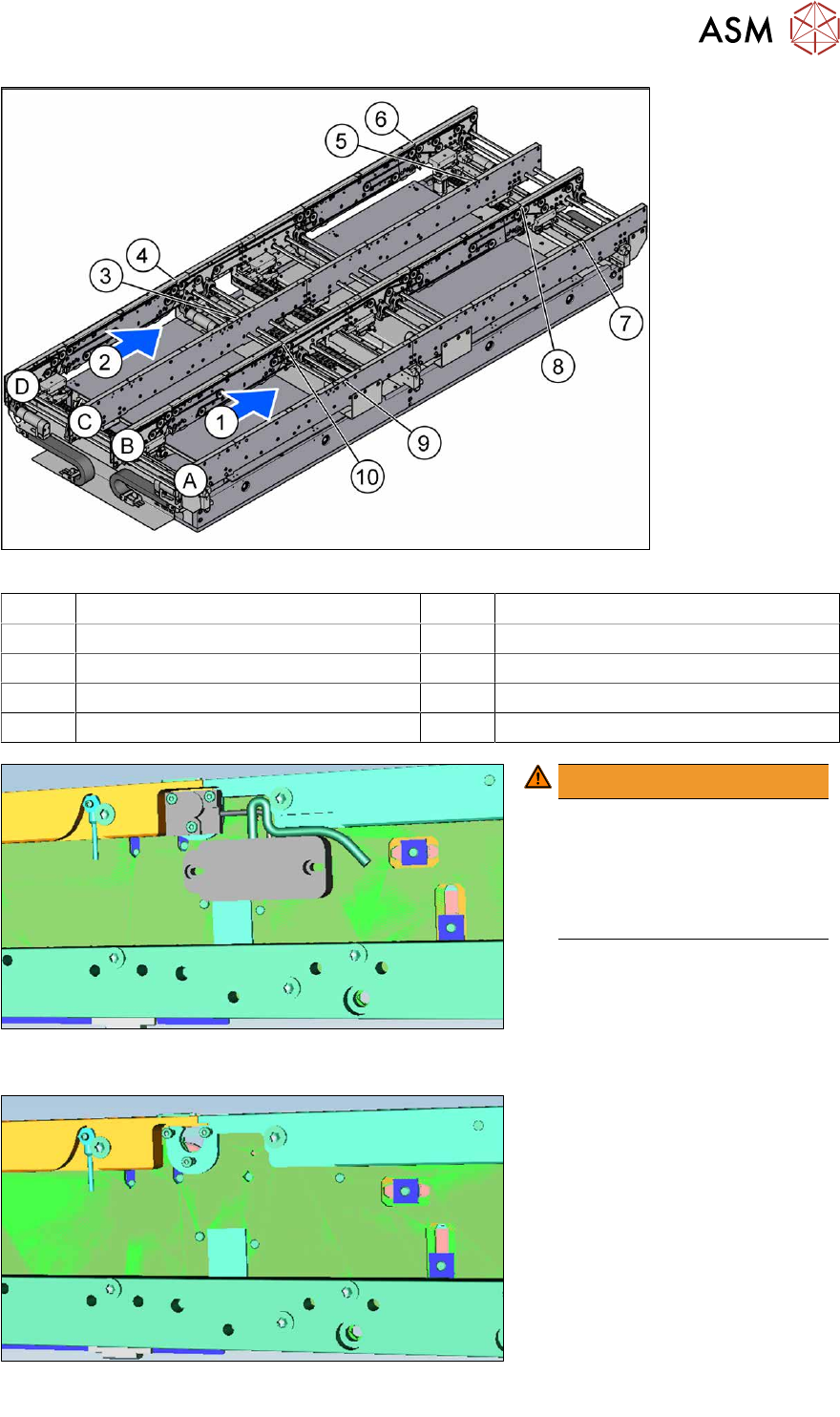
Fig.283: Overview of laser light barriers
A to D Conveyor side A to D 1, 2 Conveyor lane 1, conveyor lane 2
3 Transmitter PA1 side C 4 Receiver PA1 side D
5 Transmitter PA2 side C 6 Receiver PA2 side D
7 Transmitter PA2 side A 8 Receiver PA2 side B
9 Transmitter PA1 side A 10 Receiver PA1 side B
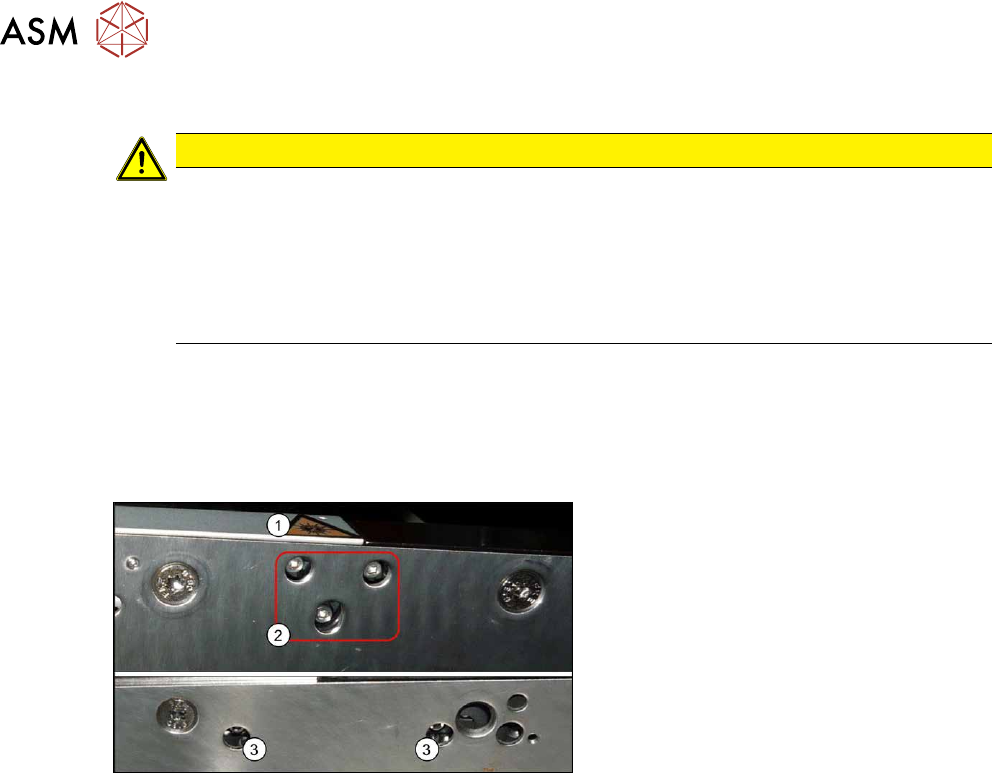
Fig.284: Laser light barrier with electronics (example of input con-
veyor used)
WARNING!
Do not dismantle the cover
plate!
The cover plate has been hid-
den for greater clarity in these
diagrams. Never dismantle the
cover plate!
.
Fig.285: Laser light barrier without electronics (example of input con-
veyor used)
7 Conveyor
7.8 Laser light barriers, fiber optic cable and PCB sensors
218 Service Manual SIPLACE X-Series S (from Hxxxx) 01/2021
Removal
CAUTION
Move the conveyor sides carefully!
The clamping and guide rails are a key stabilizing element for the conveyor side, which is
then less stable once they have been removed.
► Move the opened conveyor sides very carefully.
► Make sure that the sides are always pushed equally on the left and right.
► Make sure that you do not distort the sides.
► Switch off the machine, disconnect it from the power supply and secure it to prevent
unauthorized reactivation.
1.2 "Preparatory work..." [}16]
► Dismantle the two clamping rails/belt guides on the transmitter/receiver.
7.7.3 "Replacing the Clamping Rail/Belt Guidance" [}210]
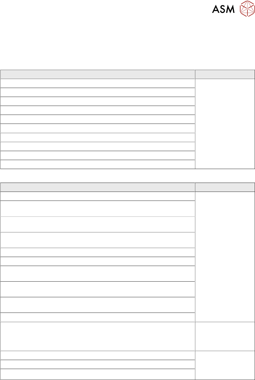
Fig.286: Fastening screws
The transmitters are always near the laser
warning labels(1)
. The receivers are always
on the opposite side walls.
► Transmitter: Remove the three fasten-
ing screws(2)
. Make sure that no parts
fall into the conveyor side wall.
► Receiver: Remove the two fastening
screws (3)
. Make sure that no parts fall
into the conveyor side wall.
► Unplug the electrical connection.
Installation
Follow the removal instructions in reverse order for installation. Also observe the following instruc-
tions:
► Reconnect the transmitter/receiver before installation.
► Make sure that all the other cables in the conveyor rail are run under the transmitter/receiver.
There is a particular lack of space at the transmitters.
If needed, the screw behind the housing can be loosened and replaced with a shorter screw
(8mm).
The screws could also be in the way of the idler pulleys.
See the following diagrams for details.
► Use the bushing for the bottom screw. This screw is used to fix the sensor.
The two upper screws are used to adjust the laser beam.
► The transmitters are fixed hand-tight with the lower screw and adjusted with the top two
screws.
► Check the setting for the transmitter/receiver and correct if necessary.
7.8.3 "Checking the laser light barrier" [}222]
7.8.4 "Correcting the Laser Light Barrier Setting" [}225]
► Teach the PCB sensors using the station software.
7.8.9
"Teaching the PCB sensors (SW70x)" [}240]
7 Conveyor
7.8 Laser light barriers, fiber optic cable and PCB sensors
Service Manual SIPLACE X-Series S (from Hxxxx) 01/2021 219
7.8.2 Replacing the Laser Light Barrier Cable
Parts, equipment and tools
Select the correct spare cable:
Motor cable
Part to be replaced Correct spare part
[03088532‑xx] Motor cable belt motor input lane-1 L=730 mm Motor cable belt mo-
tor input lane 2
L=2170 mm
[03088863‑xx]
[03088533‑xx] Motor cable belt motor placement position 1 lane 1 L=1640 mm
[03088534‑xx] Motor cable belt motor intermediate position lane 1 L=1260mm
[03088536‑xx] Motor cable belt motor placement position 2 lane 1 L=1650 mm
[03088537‑xx] Motor cable belt motor output lane 1 L=730 mm
[03088538‑xx] Motor cable belt motor input lane 2 L=730 mm
[03088541‑xx] Motor cable belt motor placement position 1 lane 2 L=1650 mm
[03088542‑xx] Motor cable belt motor intermediate position lane 2 L=1490mm
[03088543‑xx] Motor cable belt motor placement position 2lane 2 L=1650 mm
[03088544‑xx] Motor cable belt motor output lane 2 L=730 mm
Sensor cable
Part to be replaced Correct spare part
[03088545‑xx] Sensor cable belt motor input lane 1 L=760 mm Sensor cable belt mo-
tor input lane 2
L=2180 mm
[03088871‑xx]
[03088547‑xx] Sensor cable belt motor placement position 1 lane 1
L=1680 mm
[03088549‑xx] Sensor cable belt motor intermediate position lane 1
L=1500 mm
[03088551‑xx] Sensor cable belt motor placement position 2 lane 1
L=1680 mm
[03088552‑xx] Sensor cable belt motor output lane 1 L=760 mm
[03088553‑xx] Sensor cable belt motor input lane 2 L=760 mm
[03088554‑xx] Sensor cable belt motor placement position 1 lane 2
L=1680 mm
[03088555‑xx] Sensor cable belt motor intermediate position lane 2
L=1220 mm
[03088556‑xx] Sensor cable belt motor placement position 2 lane 2
L=1690 mm
[03088557‑xx] Sensor cable belt motor output lane 2 L=760 mm
[03092519‑xx] Sensor cable W51 laser side panel C2 L=1530 mm Sensor cable W46
laser side panel C1
L=1630 mm
[03092514‑xx]
[03088491‑xx] Sensor cable W30 sensor 1 side panel B1 L=1220 mm Sensor cable W41
sensor 1 side panel
B2 L=2170
[03088495‑xx]
[03088492‑xx] sensor cable W31 sensor 2 side panel B1 L=1590 mm
[03088496‑xx] sensor cable W42 sensor 2 side panel B2 L=1660 mm