00198829-01_SM_X-Series-S_Hxxxx_EN.pdf - 第316页
9 Component feeding 9.2 COT insert 316 Service Manual SIPLACE X-Series S (from Hxxxx) 01/2021 Installation ► Set the DIP switches on the FCU (see below). ► Place the connection cable in the recess and carefully push in t…
9 Component feeding
9.2 COT insert
Service Manual SIPLACE X-Series S (from Hxxxx) 01/2021 315
9.2.4 Replacing the Feeder Control Unit (FCU)
Parts, equipment and tools
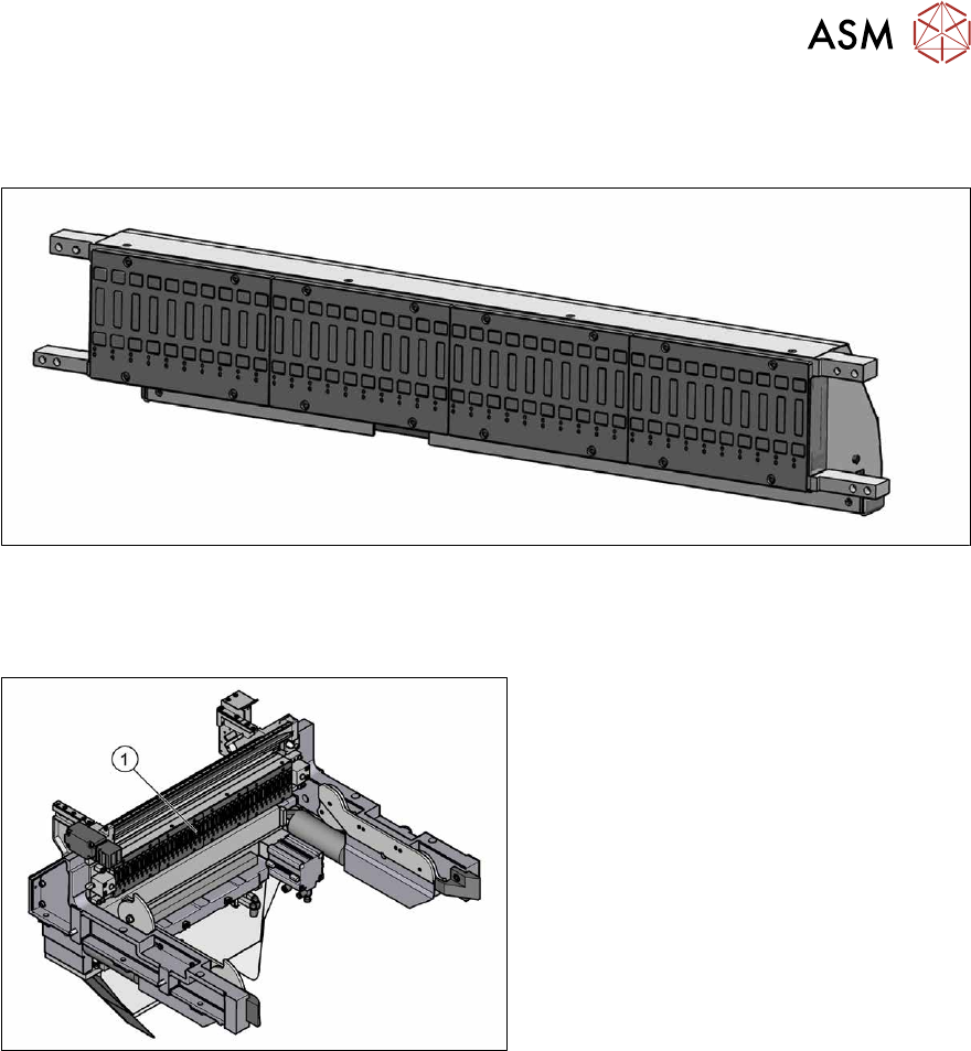
Fig.442: X-FCU V3, X-Series [03170613S01]
●
X-FCU V3, X-Series [03170613Sxx]
Overview
Fig.443: FCU on COTi
1. Feeder control unit (FCU)
The FCU is installed at the locations in the
component trolley feed device.
Removal
► Switch off the machine, disconnect it from the power supply and secure it to prevent
unauthorized reactivation.
1.2 "Preparatory work..." [}16]
► Dismantle the feeder unlocking rail.
► Remove the screws fastening the FCU. Depending on the version, there will be four or six
screws.
► Dismantle the cover plate over the cables.
► Label all cables and the positions of the connectors plugged into the terminal strip of the FCU.
► Unplug all electrical connections from the terminal strip of the FCU.
► Carefully lever the FCU out of the locating pins.
► Remove the earth terminal.
9 Component feeding
9.2 COT insert
316 Service Manual SIPLACE X-Series S (from Hxxxx) 01/2021
Installation
► Set the DIP switches on the FCU (see below).
► Place the connection cable in the recess and carefully push in the new FCU. Make sure that
you do not squash any cables.
► Pull the ends of the cables out from under the terminal strip.
► Plug in all electrical connections as labeled on the terminal strip.
► Refit the cover plate and the FCU.
Further installation is performed by following the above instructions in the reverse order.
Further information
For more information, particularly in the event of firmware problems, read the technical information
"X-FCU, 80MHz assembly" [DE:TI2019‑05D03] [EN:TI2019‑05E03].
Board description
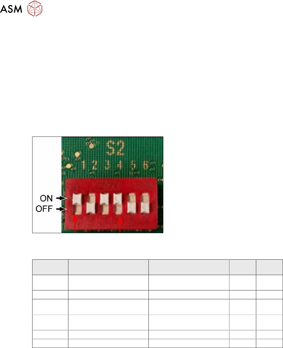
Fig.444: DIP switch S2 (example of FCU 40-fold shown)
► Set the DIP switch according to your
configuration.
DIP switch S2
S2 ON OFF 40 fold
FCU
60 fold
FCU
S2-SW1 Test mode for reject bins dis-
abled
Test mode for reject bins en-
abled
ON ON
S2-SW2 60-fold FCU 40 fold FCU OFF ON
S2-SW3 Without feed control
With virtual button
With feed control
Without virtual button
ON ON
S2-SW4 With tape cutter and NC func-
tion
Without tape cutter and NC
function
ON ON
S2-SW5 Not used Not used OFF ON
S2-SW6 Not used Not used OFF ON
9 Component feeding
9.2 COT insert
Service Manual SIPLACE X-Series S (from Hxxxx) 01/2021 317
9.2.5 Replacing the 40-fold feeder unlock device
CAUTION
Feeder unlock device on the manual table
Replacement of the feeder unlock device on the manual table is the same as that for the
COT insert. However, you need to first dismantle the front and back sections for the manual
table.
This section describes replacement using the example of the COT insert.
Parts, equipment and tools
●
Feeder unlock device 40-fold [03011582-XX]
Overview
2
1
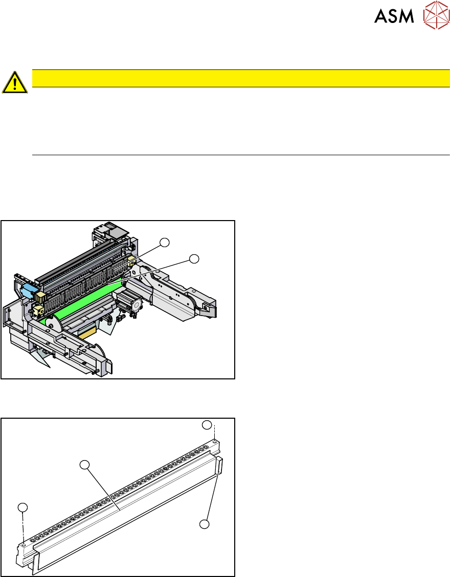
Fig.445: Feeder unlock device and FCU (example of
SIPLACE X‑Series shown)
1. Feeder unlock device (under the FCU)
2. Feeder control unit (FCU)
The feeder unlock device is installed at the
locations in the COT insert.
1
1
3
2
Fig.446: Feeder unlock device (example of SIPLACE
X‑Series shown)
1. Two fastening screws
2. Complete feeder unlock device
3. Connector for flat ribbon cable
Removal
► Switch off the machine, disconnect it from the power supply and secure it to prevent
unauthorized reactivation.
1.2 "Preparatory work..." [}16]
► Unplug the flat ribbon cable from the connector.
► Remove the two fastening screws.
► Pull the flat ribbon cable out of the side of the connector. You may have to lift the feeder un-
lock device slightly to do this.
► Lift the feeder unlocking device up and off and unplug the pneumatic connection.