00198829-01_SM_X-Series-S_Hxxxx_EN.pdf - 第341页
9 Component feeding 9.4 Docking Station for Component Trolley Service Manual SIPLACE X-Series S (from Hxxxx) 01/2021 341 Replacing the microfuse 1 3 2 Fig.481: Replacing the microfuse 1. Cover on the microfuse (T8.0A)…
9 Component feeding
9.4 Docking Station for Component Trolley
340 Service Manual SIPLACE X-Series S (from Hxxxx) 01/2021
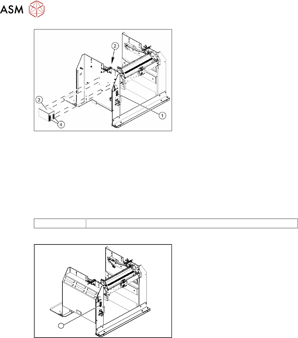
Fig.479: Removing the power pack
► Disconnect all electrical connections(4)
to the power pack(3). You may want to
mark their positions to make clear as-
signment easier later on.
► Remove the four screws(2) fastening
the power pack and then remove the
power pack.
► Connect all cables and fit the new
power pack.
► Press the ON/OFF button(1) to switch
on.
► Set the output voltage of the power pack at terminals nine and twelve:
– Standard (without BulkFeeder):
26.8 V (+/- 0.5 V)
– When using the BulkFeeders the output voltage is set permanently to 28.0V(+/‑0.5V).
► Refit the cover.
9.4.3 Replacing the micro switch
Parts
03033387‑xx Microfuse
Overview
1
Fig.480: Microfuse on docking station
1. Position of microfuse (T 8.0 A)
9 Component feeding
9.4 Docking Station for Component Trolley
Service Manual SIPLACE X-Series S (from Hxxxx) 01/2021 341
Replacing the microfuse
1
3
2
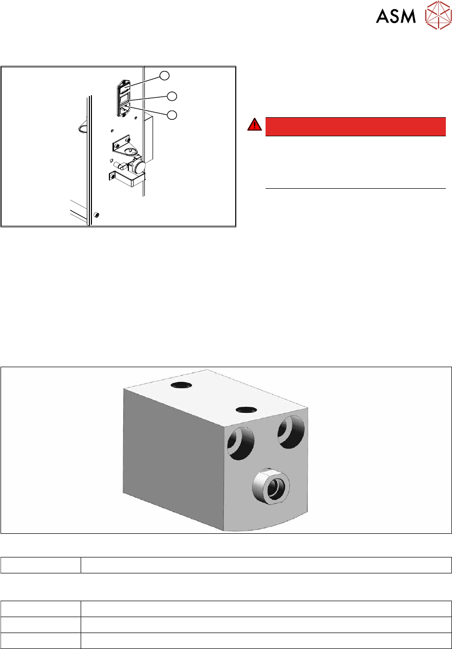
Fig.481: Replacing the microfuse
1. Cover on the microfuse (T8.0A)
2. ON / OFF switch
3. Power supply plug
DANGER!
Switch off the voltage supply
Press the ON/OFF button (2) to switch
off and then unplug the power supply
(3).
.
► Open the cover (1) on the microfuse.
► Remove the microfuse.
► Insert the new microfuse and close the cover (1).
► Connect the connection cable (3) and press the ON/OFF button to switch on (2).
9.4.4 Replacing the locking unit short-stroke cylinder
Parts
Fig.482: Short-stroke cylinder
03034831-xx Short-stroke cylinder
Equipment and tools
00353832-xx Allen key set
Lint-free cloth
Unisilikon
9 Component feeding
9.4 Docking Station for Component Trolley
342 Service Manual SIPLACE X-Series S (from Hxxxx) 01/2021
Overview
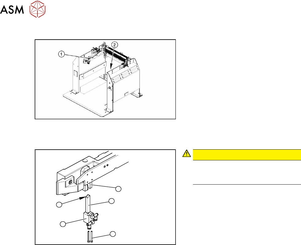
Fig.483: Locking unit left and right
1. Installation position of left locking unit
2. Installation position of right locking unit
Removal
5
1
4
3
2
Fig.484: Removing the locking unit
CAUTION!
Risk of injury
Risk of injury when disconnecting
pressurized compressed air lines.
.
► Switch off the compressed air supply.
► Remove the pneumatic connections on
the short-stroke cylinder.
► Remove the two screws (1) fastening
the short-stroke cylinder (2)
.
► Pull the short-stroke cylinder and the
locking slider(3)
downwards and out of
the guidance block(5)
.
► Unscrew the locking slider from the
short-stroke cylinder(2)
.
Installation
► Fit the locking slider onto the new short-stroke cylinder.
► Clean the locking sliders and the guidance block with a clean, lint-free cloth and lubricate both
slightly with Unisilikon.
► Move the locking slider into the guidance block, so that the beveled side (4) is pointing to the
front (in the direction of travel). This is important when moving the component trolley in.
► Fit the short-stroke cylinder with the two fastening screws.
► Reconnect to the compressed air supply.
► Switch the compressed air supply on and check that the left and right locking sliders move out
at the same time.
► If necessary, adjust the throttle valve on the short-stroke cylinder.