00198829-01_SM_X-Series-S_Hxxxx_EN.pdf - 第260页
8 Head exchange 8.4 SIPLACE C&P20 P on SIPLACE X-Series S machines 260 Service Manual SIPLACE X-Series S (from Hxxxx) 01/2021 Installation Fo llow th e remo val i nstr uct io ns i n r ev erse or de r fo r i ns tall a…
8 Head exchange
8.3 Replacing the SIPLACE C&P20 A/M
Service Manual SIPLACE X-Series S (from Hxxxx) 01/2021 259
Removal
► Switch off the machine, disconnect it from the power supply and secure it to prevent
unauthorized reactivation.
1.2 "Preparatory work..." [}16]
► Switch off the compressed air supply
5.2 "Disabling the compressed air supply" [}86]
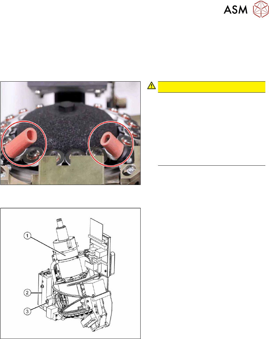
Fig.343: Hose on component sensor (example of C&P20 A
shown)
CAUTION!
The component sensor prisms, under-
neath the placement head, are easily
damaged. Take great care when dis-
mantling the head!
Protect the component sensor with two
hose sections. These are supplied with
the placement head or component
sensor and should be kept in the
machine service box. They are needed
each time you dismantle the head.
.
Fig.344: Removing the placement head
► Unplug the pneumatic connection(1).
► Disconnect the flat ribbon cable from
the placement head.
► Remove the screws fastening the strain
relief on the component camera cables
and carefully unplug the cables. While
unplugging the cables, press the
clamps on both sides of the connect-
ors.
► Loosen the two screws on the pressure
control valve (2)
.
► Undo the screw(3) from the pressure
control valve and swing the pressure
control valve to one side.
The head fastening screw near the
pressure control valve is now access-
ible.
► Unscrew all four M4 fastening screws with a long Torx key (TX20).
► Carefully lift the head out of the locating pins on the head plate.
► Placing the head into the head transport box
► If you need to perform further work on this placement head (e.g. replacing spare parts), fit the
placement head to the head mount [03056231-xx].

8 Head exchange
8.4 SIPLACE C&P20 P on SIPLACE X-Series S machines
260 Service Manual SIPLACE X-Series S (from Hxxxx) 01/2021
Installation
Follow the removal instructions in reverse order for installation. Also observe the following instructions:
► If you replace the head without component camera, you will need to fit the old camera into the
new head. Read the service manual for your placement head for more information.
► The retrofit kit "Vacuum pump mode C&P20" [00119790‑xx] must be fitted for operation in the
vacuum pump mode. This contains the "Aperture ring assembly C&P20" [03046348‑xx].
Attention: This aperture ring may not be used for the SIPLACE C&P20P/M2/P2/M3.
Read the respective vacuum pump assembly instructions for more details.
► Make sure that the assembly position on the head plate is correct.
► Tighten the four head fastening screws (M4, TX20) with a torque of 2.7 Nm.
NOTICE
Various hose lengths on SIPLACE X-Series S
The hose to the pressure control valve will vary in length, depending on the installation loc-
ation (standard gantry or rotated gantry).
► Shorten or replace the hose, where necessary.
See also
2 8.9 "Installation Positions on the Head Plate" [}278]
8.4 SIPLACE C&P20 P on SIPLACE X-Series S machines
NOTICE
Vacuum pump/compressed air mode on SIPLACE X-Series S machines
► Compressed air mode: if the SIPLACE C&P20 P is operated without a vacuum
pump, you must convert the head to compressed air mode. You will need the "Conver-
sion kit for compressed air mode SIPLACE C&P20P" [03106765‑xx].
► Vacuum pump mode (default): If the SIPLACE C&P20 P is operated with a vacuum
pump, you will need the "Upgrade kit pressure sensor vacuum C&P20P for SIPLACE
X‑SeriesS" [03108457‑xx].
8.5 Replacing the SIPLACE C&P20P/M2
NOTICE
Vacuum test
► If required, perform a vacuum test before removing the placement head.
Read the "Service manual Vacuum test at C&P placement head" [DE+EN:
00196101‑xx] for this.
NOTICE
Prerequisites for the SIPLACE C&P20P
The following additional conditions must be fulfilled for operating a SIPLACE C&P20P:
► Head interface - at least function state [03091013-03] / [03091023-03]
► Base adapter - minimum function state [03055516-06] / [03045647-08]
► MHCU – at least function state [03090990-03]
► Nozzle changers [03103649-xx] must be used.
► Nozzle station - at least function state [03073328-02]
NOTICE
Fast Hardware Exchange (FHE)
► Observe the instructions in section 8.1 "Fast Hardware Exchange" [}253] when ex-
changing a head.
8 Head exchange
8.5 Replacing the SIPLACE C&P20P/M2
Service Manual SIPLACE X-Series S (from Hxxxx) 01/2021 261
Parts, equipment and tools
●
SIPLACE C&P20P [03091157‑xx] (without camera)
●
SIPLACE C&P20M2 [03125907Sxx] (without camera)
NOTICE
Vacuum pump/compressed air operation
As a spare part, the head is prepared for vacuum pump operation and is fitted with the
"Aperture ring assembly C&P20 P" [03116883‑xx].
► The SIPLACE C&P20P/M2 must be converted with the conversion kit "Compressed
air C&P20x" [03106765‑xx] or with the "Holding circuit assembly
C&P20" [03005123Sxx] for operation in compressed air mode.
●
Torx screwdriver ESD 1.0-5.0 Nm [03078400-xx]
●
Bit holder for TorqueVario screwdriver [03078706-xx]
●
Extension/straight TX20 [03073256-xx]
●
Torx offset screwdriver TX8 [03080081-xx]
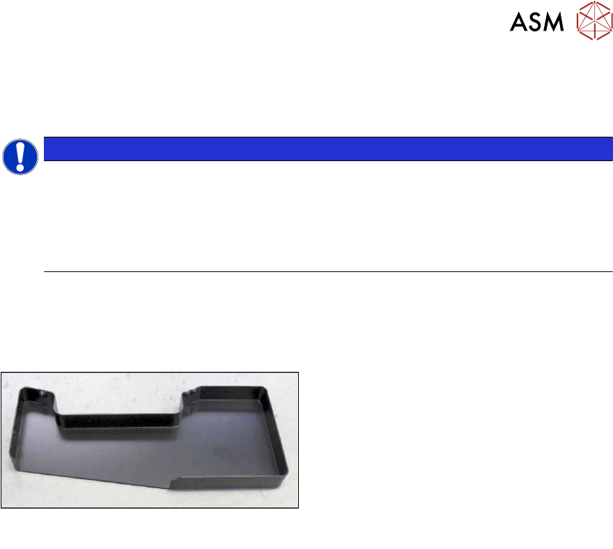
Fig.345: Component sensor protective cap
[03092400‑xx]
●
Component sensor protective cap
[03092400‑xx]
●
Calibration tool version SST23 [03034148-
xx]
●
Calibration tool SST48/49 [03157023-xx]
For additional work to the placement head:
●
Head mount [03056231‑xx]
●
Service manual "SIPLACE C&P20P" [DE:00197489‑xx] [EN:00197490‑xx]
●
Job Card "Preventive Maintenance C&P20P" [DE:00197529‑xx] [EN:00197528‑xx] (other
languages available)
If needed, for vacuum pump operation:
●
Assembly instructions "Option Vacuum Pump SIPLACE X-Series S from Hxxxx " [DEEN:
00198599‑xx]